Professional Injection Mold Maker in China
Holly has a mold design team with more than 20 years of design experience. We have designed more than 7500 sets of molds, including automotive, medical, optical, home appliances, office equipment, etc. In order to ensure the quality of mold design, we have gone through DFM, Moldflow, 2D & 3D mold design, mold design approval and other processes. Every step is done through communication and consultation with the client to ensure that the client’s requirements can be met.
After 20 years of development, Hawley has established its own strict mold design standards, which can fully meet the requirements of European, American, Asian and other markets.

Featured Mold Design Process

DFM Report
DFM Analysis Service allows product designers to identify and resolve any issues that may arise during the manufacturing phase to reduce costs. Depending on the type of manufacturing process, DFM practices have guidelines that help to precisely define various tolerances, rules, and common manufacturing checks.

Moldflow Analysis
MoldFlow provides simulation tools for injection mold design. Through iterative molding simulations, our team can optimize product design, mold design, and prevent multiple mold modifications, reducing cost and time.

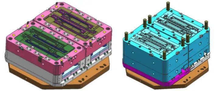
2D & 3D Mold design
Through 2D and 3D design, we can help customers to find out the required changes or improvements to the product. We can check all the details in the mould to avoid the possibility of mistakes.

Mold Approval
Holly will evaluate the mold design and communicate with our customers until both parties agree on the mold design. In the mold design stage, we will share with customers: DFM analysis report, Moldflow analysis report, 2D mold design, 3D mold design
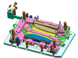
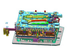
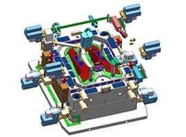
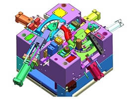
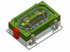
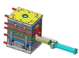
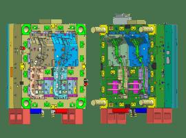
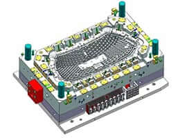
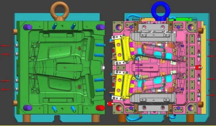
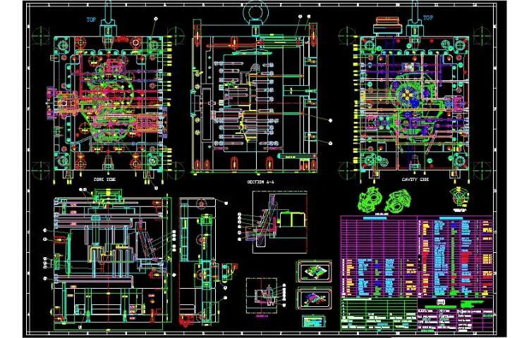
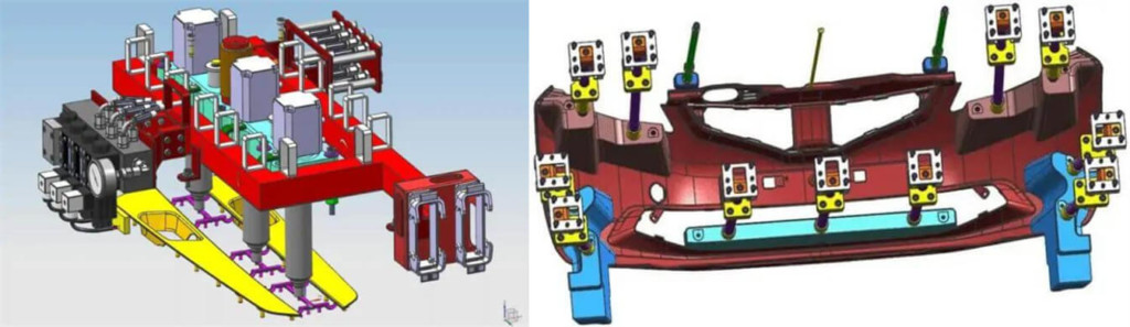
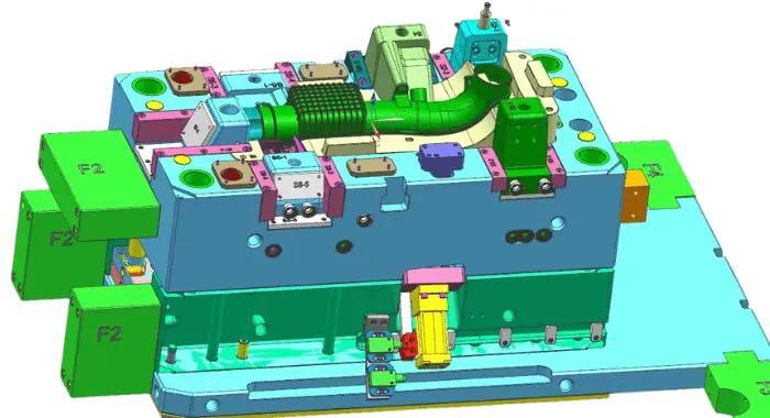
Our Recent Projects
Injection Mold Design Service – Ultimate FAQ Guide
In the following guide, you will know everything about Injection Mold Design.
Injection Mold Design – Ultimate FAQ Guide
As an expert in mold design for 20 years, Holly can turn your ideas into reality. Here, we share this guide with you. Trust that you can get most of your enquiries and our company from it. If you find out what we can do to support you, please feel free to contact us. We are available 24/7/365.
Q1: What does mold design mean?
Die design refers to people who are engaged in the digital design of cavity molds, cold stamping molds and other enterprise molds on the basis of traditional mold design, make full use of digital design tools, improve the quality of mold design, and shorten the mold design cycle.
Q2: Which software can be used for mold design?
Software for mold design includes UG, Pro/Engineer, AutoCAD, Cimatron, PowerMill Hypermill, Solidworks, WORKNC, Solid Edge, CATIA, etc.
For simple molds, CAD software is fast and easy to use; for molds with complex structures and surfaces, Pro-E, UG, Mastercam, Solidworks are all good choices. Pro-E or UG is usually used for drawing and production. Each software has its own characteristics. An important factor in the choice is which one the mold designer is better at or prefers to use.
Q3: How many steps are there in mold design?
In the actual design process, we need to consider the order of 2D drawings or 3D drawings according to the requirements of the design content. Our mold design steps are as follows FYR.
- According to the 2D and 3D drawings of the customized plastic parts, organize the design data, analyze the structure, shape, and assembly size of the plastic parts (for example, analyze the rationality of the demolding angle during the molding process) to confirm whether the parameters of the injection molding machine are consistent with the mold. , cavity, production batch, steel requirements and other relevant dimensions are matched, and then these data are converted into design instructions.
- We will determine the mold type, the overall structure, the number of mold cavities, and the cavity layout.
- The parting surface is determined by 3D modeling parting or 2D drawing after modeling).
- We will determine the type of injection molding system, perform Moldflow analysis, and determine the form, location and number of gates.
- Determine the lateral core-pulling structure and the lifter mechanism.
- Confirm the mosaic structure.
- Ejection early return system design.
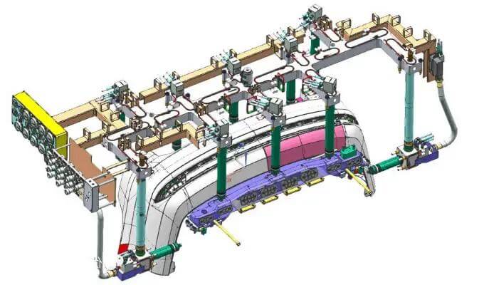
- Design of heating and cooling system.
- Design of guide positioning system.
- Selection of die base (size of template, cavity, core, etc.). Make the assembly drawing of the mold base, and try to design it according to the standard mold base.
Q4: What is the key point of mold design?
- The overall layout of the mold is reasonable
- Parting surface selection
- Arrangement of 3 runners, selection of glue inlet
- Ejection device
- Arrangements for water transport
- Exhaust Options
- Pay attention to the drafting angle, the extraction of inserts, the treatment of friction angle, and the selection of material shrinkage when splitting the mold
- The machining drawings should be detailed but simple.
In conclusion, the mold design must take into account the mold release ability! Easy to handle and eject!
Q5: What should be paid attention to in the design of hot runner mold?
Determine the gate position according to the structure of the plastic part and the requirements for use. As long as the structure allows, the nozzles and nozzle heads in the fixed mold insert do not interfere with the molding structure, and the gate of the hot runner system can be located anywhere in the plastic part. The injection gate location for conventional plastic injection molding is usually chosen empirically. For large and complex shaped plastic parts, computer-aided analysis (CAE) can be used to simulate the position of the injection gate, simulate the flow of molten plastic in the cavity, analyze the cooling effect of each part of the mold, and determine the ideal gate position.
- Determine the nozzle shape of the hot runner system. Product materials and usage characteristics are the key factors in choosing the shape of the nozzle, and the production batch of plastic parts and the manufacturing cost of the mold are also important factors in choosing the shape of the nozzle.
- The number of cavities in each mold is determined by the production batch of the product and the tonnage of the injection molding machine.
- The number of nozzles is determined by the position of the glue inlet and the number of cavities in each mold. If you form a product, choose a mold and a feed port, you only need one nozzle, i.e. use a single-head hot runner system; if you form a product, choose a mold with multiple cavities or a mold with a cavity with more than two A brief summary If you want to open the nozzle, you need multiple nozzles, that is, a multi-head using a hot runner system, in addition to the cross-runner mold structure.
- Determine the radial size of the nozzle according to the weight of the plastic part and the number of nozzles. Currently, nozzles of the same shape are available in multiple size series to meet the molding requirements of plastic parts in different weight ranges.
- Determine the size of the mold structure according to the structure of the plastic parts, then select the standard length of the nozzle series according to the thickness of the fixed insert and the fixed template, and finally adjust the thickness and other dimensions of the fixed template with the hot runner system.
- Determine the shape of the hot runner fixing plate according to the shape of the hot runner plate, arrange the power line lead groove on the hot runner plate, and design enough cooling water circuits near the hot runner plate, nozzle and nozzle head.
Q6: What should be paid attention to in the design of hot runner?
Hot runner injection is always used for injection mold design, so what should be paid attention to when designing hot runner?
- The guidepost of the hot nozzle needs to be protected, the height must be higher than the hot nozzle, and two locking screws are required. For easy assembly and disassembly, it cannot be locked from the panel to the end.
- The ground side needs to increase the drainage channel, the depth is 3-5mm, and the pressurized line plate. The cavity can be reduced by using the cutting body sent by the hot nozzle company, but there should be no sharp corners in the frame to avoid scratching the hot nozzle or the hot nozzle line.
- Open hot nozzle, the sealing part is only 3mm, and the top surface of the hot nozzle is 0.2-0.5mm lower than the runner or PL, which is used to release the thermal expansion of the hot nozzle. The cavity in the core is imaged from the Hot Nozzle Company. The file has been deleted and no further changes can be made.
- EWIKON hot nozzle point, keep 0.3mm straight at the sharp point to avoid repeated wear of the nozzle and damage to the steel here.
- For MOLD MASTER to open the hot nozzle to feed glue, it is necessary to avoid the thermal expansion of the hot nozzle by 0.2mm in the air according to the drawings of the hot nozzle company. Elsewhere, cavity cutting is performed according to drawings given by Hot Nozzle Company.
- Use MOLDASTER needle valve hot nozzle to send glue, leave 0.7mm for sealing, and cut other parts according to the drawings given by the hot nozzle company.
- When GUNTHER hot nozzle is dispensing, it needs to keep 0.3mm straight to avoid repeated wear of the nozzle and damage to the steel.
Q7. How to judge whether the mold design is reasonable?
Mold design is mainly reflected in four aspects.
- The quality of the plastic products produced (appearance quality and dimensional stability).
- It is convenient, fast and concise, which saves money and manpower in the process of processing and manufacturing, and also leaves room for mold revision and improvement.
- The mold is safe and reliable to use and easy to maintain.
- In injection molding, sometimes there is a shorter molding cycle and longer service life, and there is also a reasonable mold manufacturing process.
Q8. What should be paid attention to in the design of gate type in mold design?
For mold design, gate design is usually based on experience, the size of the gate depends on the cross-sectional area and gate length:
- The cross-sectional area of the gate should be as small as possible, and the length of the channel should be as short as possible to ensure the appearance of the finished product and reduce the pressure loss when the plastic passes through.
- The gate must be narrow to facilitate cold forming and prevent excessive plastic backflow, so the gate should be located in the center of the runner.
Q9. How many gate types are there in the mold design?
In mold design, in order to obtain the best filling conditions, the type of gate must be carefully selected. Common gates are gate, side gate, overlapping gate, fan gate, diaphragm gate, ring gate, film gate, needle tip gate, submerged gate, tablet gate, hook gate Wait.
Q10. Why should die design choose edge date?
In the in-mold design, the side gate is a commonly used gate type, and its structure is also the simplest one. Only work on one side of the mold. This gate connects the runner to the finished product.
Here are a few reasons why mold designs choose edge gates.
- The cross-sectional area is simple and easy to process.
- The size is easy and precise to control, and the speed of improvement is fast.
- When filling plastic, the finished product is easy to control.
- It is susceptible to cooling and solidification of the gate and all plastics.
Q11: What are the advantages of fan gate mold design?
Fan gate is one of the gate types for mold design. Here are some advantages of this door type for your reference.
- Suitable for large thin-walled injection molding products.
- When the resin flows into the mold, the plastic starts to flow and expand from a thin shape, forming a plastic with good fluidity, reducing the flow pattern and water collection pattern.
- The fan door is suitable for any plastic, especially PMMA, except rigid PVC.
Q12. What are the requirements of the mold design for the ejector system?
The requirement of the ejector system is to release the mold accurately and without deformation within the specified time. Here are 7 points to consider in mold design.
- The ejection stroke generally stipulates that the ejected product is 5~10mm away from the mold. For some simple cylindrical products, the demoulding slope is large, and the stroke can reach 2/3 of the product depth. Don’t make it too long, because the ejector rod is very thin and has a long stroke, which can easily damage the ejector rod.
- The reset lever (reset lever) must be set in the ejection system to help the ejection lever return. During the ejection process, the ejector base plate bears a large ejection pressure. When the strength and stiffness are insufficient, the flexible deformation affects the movement of the catapult. Pay attention to the screw connection (need to be screwed in from the backing plate to the fixing plate) to avoid insufficient space for the wrench.
- The relationship between the top of the ejector pin and the core (or cavity) plane should theoretically be on the same plane, which is convenient for mold manufacturing and assembly. In actual production, most of the end faces of the ejector pin exceed or lower the core surface (or cavity) by 0.05~0.1mm. When there are convex pits on the inner surface of the product, it should be determined in consultation with the designer.
- The shape and size of the push rod. Unless the shape of the product is restricted, another thimble must be used. Generally speaking, a cylindrical ejector is used, and an elongated ejector with a diameter of less than 3mm should be avoided.
- Due to the large size of the fixed plate of the ejector pin and the backing plate, the span between the backing plates of the movable mold is increased. Under higher injection pressure, the movable die pad may be deformed, resulting in poor push pins or jam. In addition to increasing the thickness of the movable die pad to improve its rigidity, the support column can also be set between the movable die fixing plate and the backplate.
- When the product has a large output or a long ejection stroke, use a thin ejector rod, when the ejector tube is used for ejection and the movable die fixing plate is equipped with a slender core, which is used to protect the push pins (or long core). The movement is stable, the ejection system needs to be equipped with a guide device, and there are positioning pins between the movable template, the seat cushion rod and the movable mold fixed plate to ensure the positioning accuracy.
- If there is plastic around the steel part of the product, it will be difficult to demould. This is due to the phenomenon of “holding” of the steel part due to shrinkage stress caused by the cooled plastic melt. Therefore, these places (ribs, columns) should be considered.
Q13. How many exhaust methods are there in the mold design?
In the mold design, the injection mold exhaust system is the exhaust of the cavity and the gating system, which mainly includes the air in the cavity, the air in the runner, and the steam in the plastic at high temperatures. These gases must be discharged in time so as not to affect the quality of the plastic parts. The exhaust methods in the injection mold include the following 7 ways:
- Parting surface (including exhaust groove);
- Insert mating surface;
- Fit surface of push rod or push tube and inner mold insert;
- Side core pulling mechanism
- Install ventilation needles or pins to exhaust the trapped air;
- Steel exhaust;
- Exhaust valve.
Q14. What are the design principles of the exhaust system in mold design?
In the mold design, according to the seven exhaust methods of the exhaust system, the general design principles of the exhaust system need to follow these rules. The vent slot can only vent, not melt the plastic.
- Different plastics have different depths of vent grooves due to different viscosities.
- The cavity should be designed with an exhaust slot, and the runner and the cold material cavity should also be designed with an exhaust slot, so that the gas in the gate system can enter the cavity as little as possible.
- The vent groove must be open to the outside of the die base, especially when venting through the insert, vent pin or vent insert.
- Use a milling machine to machine as many vent grooves as possible. After treatment, use 320 sandpaper to remove knife marks. Avoid using the grinder on the exhaust slot. The surface of the grinder is too smooth, and the exhaust effect is usually not good.
- The vent groove on the parting surface should be set on the side of the cavity, usually designed on the fixed die insert.
- There should be a 45° chamfer on both sides of the exhaust groove.
Q15. How to design the parting surface of the mold?
For mold design, the design of the parting surface is very important, because it will directly affect the mold structure, the difficulty of mold processing, and the cost of mold design and manufacturing. Here are some tips for parting surface design in mold design.
- Comply with the demoulding of plastic parts: In order to make the plastic parts take out from the mold, the parting surface should be set at the part of the largest size of the plastic part’s cross-section.
- The number and shape of the parting surface: usually there is only one perpendicular to the parting surface. Mould opening movement direction. The determination of fractal surface should be based on the principle of convenient mold manufacturing and demoulding.
- Selection of cavity: try to prevent the formation of side holes and cuts, and avoid the use of more complex mold structures.
- Ensure the surface quality: try not to choose the smooth outer surface of the plastic part as the parting surface, so as not to affect the appearance quality of the plastic part; place the required parts coaxially on the same side of the parting surface. In order to ensure the coaxiality of the plastic parts, it is necessary to consider reducing the size difference caused by the small and large ends of the plastic parts.
- Facilitate the demoulding of plastic parts: Since the demoulding mechanism of the mold is usually set on one side of the movable mold, try to keep the plastic parts After the mold is opened, the label is on the side of the movable mold.
- Take into account the pull distance of the side shaft. Generally speaking, the lateral axis pulling distance of the mechanical parting core pulling mechanism is relatively small. Therefore, when selecting the parting surface, the core pulling direction or the parting distance should be placed in the opening and closing directions of the movable and fixed molds. The short axis draw distance is used for side parting or core pulling. And it is necessary to pay attention to pulling the side core pulling on the side of the movable mold to avoid core pulling of the fixed mold.
- Locking the mold is required: the lateral clamping force is small, so for large plastic parts with a larger projected area, the larger the direction of the projected area should be placed in the clamping direction of the moving and fixed mold, and the direction with the smaller projected area is considered is the lateral parting surface.
- Conducive to exhaust. When the parting surface is used as the main exhaust passage, the parting surface should be designed at the end of the plastic flow to facilitate exhaust.
- Mold parts are easy to process.
Q16. What is the function of mold design?
Mold inserts refer to the irregular mold accessories used to be embedded in the mold, which play the role of fixing the template and filling the space between the template. It has the following functions.
- Conducive to venting.
- Easy process.
- Good polishing effect.
- Simple markup.
- The places that are easily damaged or worn can be replaced.
- Because the plug-in board is conducive to heat dissipation.
Q17. What should be paid attention to in slider design in mold design?
Here are some things to keep in mind when designing your slideshow.
- 1The core pulling distance should be at least 3mm greater than the depth of the notch.
- The slide must be designed with a collision surface. In general, the data on the part drawing should be taken from the datum plane, and the datum plane should not be arbitrarily changed during processing.
- If the plastic position of the core slider has requirements for appearance and clamping, the slider must be extended into the cavity side as a tubular position to facilitate subsequent mold polishing.
- Handling of the inclination of the sealing position on the core side.
- When the core slider extends into the plastic area, the extending part must be inclined to facilitate mold installation and reduce friction.
- The slideway and its accessories should be easy to install and remove.
- The slide should avoid sharp angles.
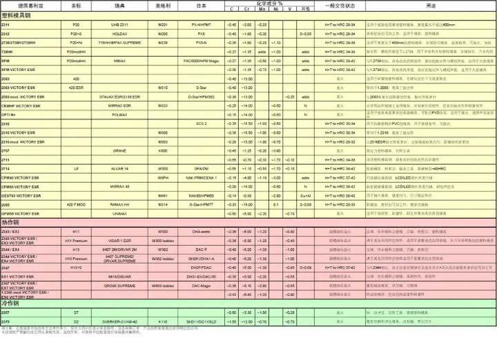
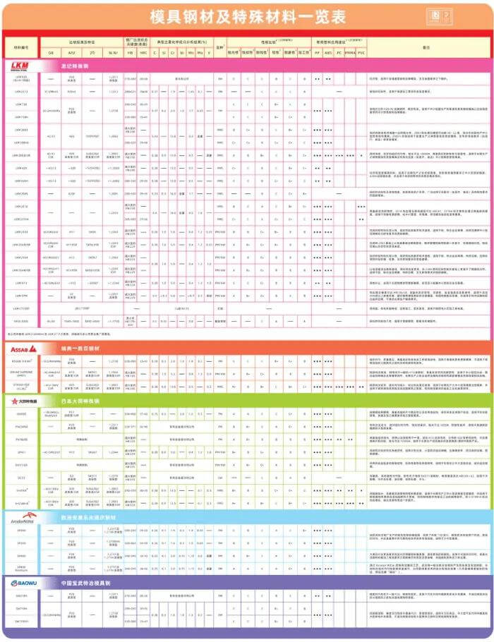
Q18. What steel options should we consider when designing molds?
In mold design, the selection of molding steel needs to follow three principles: meeting work requirements such as wear resistance, strength, and toughness; meeting process requirements; and consistent economic applicability.
1. Meet the job requirements
a) Wear Resistance
One of the most fundamental and important properties of a mold is its wear resistance. Hardness is the main factor affecting wear resistance. In general, the harder the mold parts are, the smaller the amount of wear and the better the wear resistance. In addition, wear resistance is also affected by the type, quantity, shape, size, and distribution of carbides in the material.
B) Strength
The working environment of the mold is usually very harsh, and some often bear a large impact load, resulting in brittle fracture. In order to prevent the sudden brittle fracture of the mold parts during the working process, the mold must have high strength and toughness. The toughness of the mold mainly depends on the carbon content, grain size and organizational state of the material.
C) Fatigue fracture performance
In the working process of the mold, fatigue fracture is often caused by the long-term action of cyclic stress. Fatigue fracture performance of the mold is largely determined by its strength, toughness, hardness, and inclusion content.
D) high-temperature performance
When the working temperature of the mold is high, the hardness and strength will decrease, resulting in early wear or plastic deformation failure of the mold. Therefore, the mold material should have high stability against tempering to ensure that the mold has high hardness and strength at standard operating temperatures.
E) heat and cold fatigue resistance
Some molds are in a state of repeated heating and cooling during the working process, resulting in tensile and compressive stress on the surface of the cavity, causing surface cracks and peeling, increasing friction, hindering plastic deformation, reducing dimensional accuracy, and causing mold failure. Hot and cold fatigue is one of the main forms of thermal tool failure, so such molds should have high resistance to cold and heat fatigue.
F) Corrosion resistance
When some plastic molds are operated, due to the presence of chlorine and fluorine plastics, strong corrosive gases, such as human-computer interaction and high-frequency heating will be resolved, which will will erode the surface of the mold cavity, increase its roughness, and aggravate wear failure. So these molds should be corrosion resistant.
2. Meeting process requirements
The manufacture of mold generally includes several processes such as forging, cutting, and heat treatment. In order to ensure the quality of the mold and reduce the production cost, the mold design should consider that its material should have good forging ability, machinability, hardenability and grinding ability; it should also have less oxidation and desorption, carbon sensitivity and quenching. Deformation and cracking tendency.
3. In line with economical applicability
When designing the mold and selecting the mold material, the principle of the economy must be considered to reduce the manufacturing cost as much as possible. Therefore, on the premise of satisfying the performance, we first choose materials with lower prices. Unless the customer specifies the steel material.
In addition, the production and supply situation in the market should also be considered when selecting materials. The selected steel grades should be as few and concentrated as possible for easy purchasing.
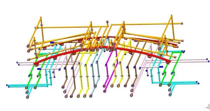
Q19. What are the design principles of the cooling system in mold design?
- On the premise that the steel material has sufficient mechanical strength, the cooling system should be arranged as close as possible to the surface of the cavity (core). The distance from the cavity should be as equal as possible to enhance cooling and make the mold temperature uniform.
- Under the premise of ensuring sufficient mechanical strength, cool the steel, the system layout should be as close as possible.
- The diameter of the cooling system should be 10mm, and the diameter of each channel should be the same as possible.
- For large molds, the cooling system can be divided into several independent circuits to increase the coolant flow, reduce pressure loss and improve heat transfer efficiency. Because the cooling circuit is too long, it will cause a large temperature gradient change, resulting in a high temperature at the end of the cooling system, thus affecting the cooling effect.
- The thick part of the product wall should be specially cooled. Or take strengthening measures at the thin wall to make the mold temperature uniform.
- We should fully consider the thermal conductivity of the mold material, and BeCu inserts can be used to dissipate heat from areas that cannot be reached by cooling and must be cooled. The cooling inlet should be located close to the gate. Due to the high temperature near the gate, this area should be cooled vigorously.
- For multi-cavity molds, try to design cooling in each cavity separately to facilitate control.
- The cooling layout should conform to the shape of the product as much as possible.
- Larger slides and angle risers also require cooling. Because the lack of cooling can affect the quality of the product.
- For the mold with a heating tube or high temperature, it is necessary to install a cooling device on the guide column to cool the guide column according to the situation to prevent the guide column from being damaged by high temperature burning during the movement.
- When the direction of the pipe joint and the plug is the same, the distance from the center to the nearest is not less than 25mm, the distance between the cooling and the product is generally not less than 10mm, and the design is as far as possible between 10mm-12mm. In addition, the alloy mold is generally 25mm. To determine the diameter of the cooling water hole, pay attention: no matter how big the mold is, the diameter of the water hole cannot exceed 14mm, otherwise it will be difficult to form cooling.
Generally speaking, the diameter of the water hole can be determined according to the average thickness of the product.
Q20. What is the principle of 2K injection mold design?
For the design of 2K injection molds, there are three principles to follow.
- First principle: Determine the viscosity of the combination of hard and soft plastics. Also, note that hard rubber has a higher melting point than soft rubber.
- The second principle: confirm that the second soft plastic and the first hard plastic do not fall off after molding.
- The third principle: Combine the company’s existing two-colour injection molding machine for mold design.