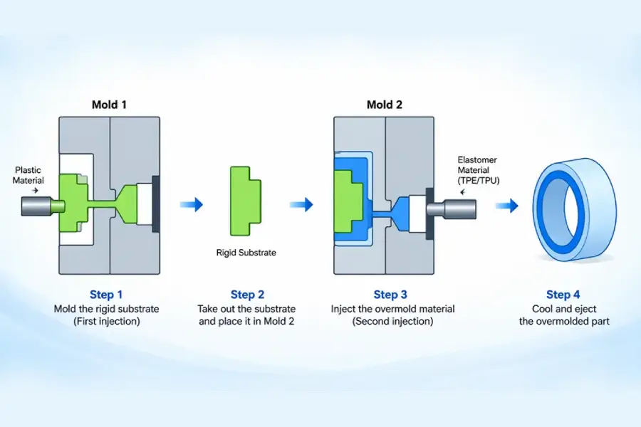
Several factors affecting the final assembly and function of gears, connectors, sensors, and medical components made by precision injection molding are material shrinkage, mold position, molding parameters, warpage, and long-term dimensional drift. Stability, repeatability and accuracy during molding process helps to ensure accuracy dimension in mass production.
This article begins with the tolerance of precision injection molding and examines the tolerance conditions of material, mold, equipment and process. It includes also the list of commonly used materials, important product design features and typical applications. It gives a reference for product design, mold development and mass production control projects, based on dimensional fluctuation, warpage, bore-size variation and post shrinkage problem found in actual production.
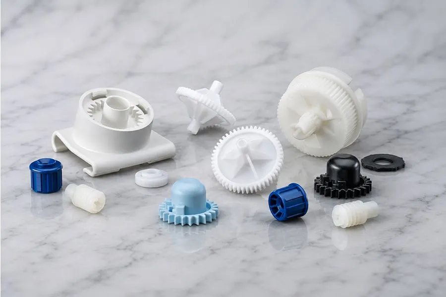
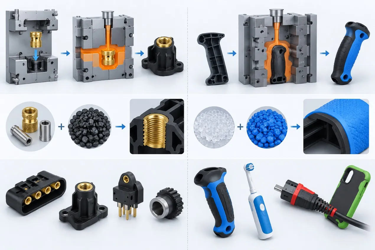
Precision Injection-Molded Product Collection
1. What Is Precision Injection Molding?
Precision Injection Molding is an injection molding method used for making plastic parts which are required to have a high degree of precision in terms of dimensions, fit or repeatability. Common uses are precision gears, structural parts for sensors, connectors, parts for diagnostic equipment, and fluid-control parts. Precision injection molding focuses on controlling Accuracy, Repeatability and Stability.
2. What Tolerances Can Precision Injection Molding Achieve?
There is no set tolerance for precision injection molding. The actual tolerance will vary depending on the material, part size, direction of measurement, wall thickness, flow direction, mold structure and if the measurement crosses a Parting Line, Slider, or Lifter. The following dimensional tolerances may be used as a reference for some small and medium precision plastic parts:
- When it comes to critical dimensions, conventional injection molding can be within ±0.10 to ±0.20 mm, precision injection molding about ±0.03 to ±0.05 mm and, under appropriate conditions, some very small features can be achieved within ±0.02 mm.
- The dimensions of the assemblies range from 10 to 50 mm and the tolerances are conventional injection molding ±0.15 – 0.25 mm, precision injection molding ± 0.05 – 0.08 mm.
- The precision mass production projects typically take Cpk ≥ 1.33 as a target, and some critical dimensions can even demand a Cpk ≥ 1.67.
3. What Determines Dimensional Stability in Precision Injection Molding?
Dimensional stability in precision injection molding mainly depends on the material, mold, equipment, molding parameters, and mold wear.
1) Consistency of Material Batches and Shrinkage Behavior
Actual Shrinkage is dependent on the type of plastics, mold temperature and pressure. The shrinkage range of POM standard test pieces is around 1.2%–2.4% for POM and 1.8%–5.0% for Celcon M90 depending on the mould temperature and pressure. For precision projects, use the same resin type and the same Grade of the resin, and track the viscosity, filler levels and moisture in the resin from batch to batch of production. In addition to this, Glass fiber reinforced materials need to be paid attention to Fiber Orientation. Shrinkage varies in a flow direction compared to the transverse direction, leading to warpage and shift in hole position.
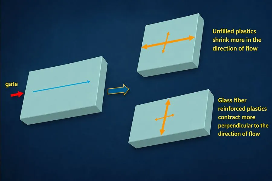
Fiber Orientation and Anisotropic Shrinkage
2) Repeatable Positioning of Critical Mold Dimensions and Moving Mechanisms
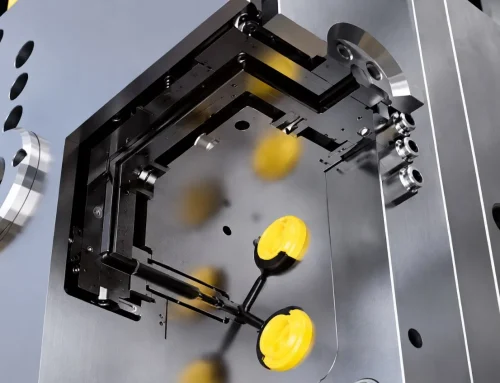
Fixed cavity dimensions must be controlled and moving mechanisms (such as sliders, inserts, and ejector pins) must be repeatably positioned in precision molds. In high precision projects, the accuracy of the critical cavities, inserts and locating features of the machine can be +/-0.005mm to +/-0.1mm, and the repeatability of the positioning of the moving mechanism is ≤+/-0.01mm. To make sure that Cavities are consistent, look at multi-cavity molds. If you’re using a fixed Core to create a bores, shut-offs or other dimensional feature, you need to use the Core steel dimensions and material shrinkage settings.
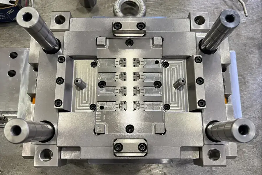
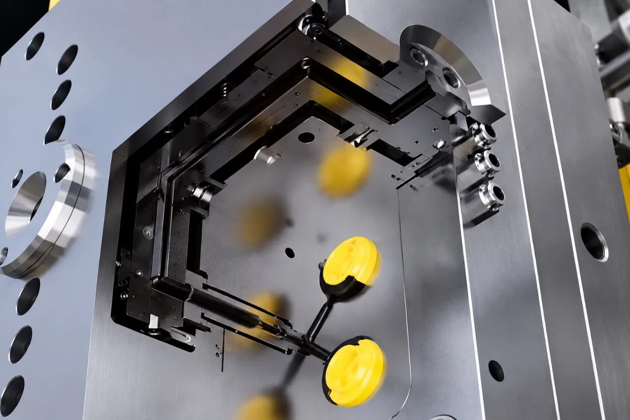
Injection Mold Core and Cavity
3) Injection Machine Repeatability and Process Variation
In general, there must be stable injection speed, injection pressure, metering and clamping control in precision injection molding. If the work is extremely difficult, closed-loop servo equipment can be used, and from the actual production data, the repeatability of pressure, injection speed can be verified.
The precision measurement results may also be influenced by ambient temperature and humidity that affect certain materials. If the dimensions of the product are important, try to regulate the production and measurement conditions according to the specifications of the material and inspection. And standardize the condition of the parts before they are measured.
4) V/P Transfer and Holding Pressure
V/P Transfer has an impact on the end of filling, Part Weight, residual stress and final dimensions. An early switch causes underfilling, undersized dimensions; a late switch causes oversized dimensions, and an increase in residual stress.
If a precision part, use a staged Holding Pressure to control shrinkage compensation and the V/P transfer point is determined via Cavity Pressure, screw position, Part Weight and dimensional changes.
5) Mold Wear
Slider, Lifter, Core, Insert, and guide structures wear during long-term operation, directly affecting dimensions or the repeatable positioning of moving mechanisms. During mass production, continuously record CTF dimensions. If a dimension trends consistently in one direction, inspect the corresponding Core, Insert, and positioning mechanism for wear and schedule maintenance or replacement as required.
4. What Materials Are Commonly Used for Precision Injection Molding?
Common materials used in precision injection molding include:
1) ABS, PC, and PC/ABS—Precision Housings and Instrument Structural Parts
ABS, PC, and PC/ABS are commonly used for consumer electronics, instrument housings, and precision assembly structures.
2) POM—Precision Gears, Sliding Parts, and Transmission Components
POM offers low friction, wear resistance, and good creep resistance. It is commonly used for miniature gears, shafts, sliding guides, and transmission clips.
3) PBT—Connectors, Sensors, and Precision Electrical Parts
PBT has low absorption of water, excellent electrical properties and good heat resistance. It is often used in connector pin headers, sensor housing or electrical structural components.
4) PA and Glass-Fiber-Reinforced PA—High-Strength Precision Structural Parts
PA6, PA66 and their glass-fiber-reinforced grades offer excellent strength, toughness and fatigue resistance, and are suitable for precision brackets and load-bearing components.
5) PPS, PEEK, and LCP—High-Temperature and High-Performance Precision Parts
PPS: Low water absorption, good heat resistance, good dimensional stability; it can be used to manufacture industrial precision parts for high temperature.
LCP: Good flowability suitable for thin wall parts, small parts and micro feature parts.
PEEK: High temperature resistance, chemical resistance and mechanical properties, it is suitable for high-performance industrial structural parts, medical devices, analytical instruments.
5. How Should Precision Injection-Molded Products Be Designed?
In precision injection molding design, it is necessary to begin with functions required and coordinate dimensions, tolerances, structural and molding conditions.
1) CTF Critical Dimensions and Datum Design
First identify the CTF dimensions, such as mating bore diameters, gear center distances, sealing surfaces, and mounting locations. Allocate tolerances according to actual functional requirements and avoid over-tightening non-functional dimensions.
Datums should correspond to actual locating surfaces, assembly surfaces, or functional centers. Use the same datum system for design, mold machining, and inspection wherever possible to reduce positional error caused by datum conversion.
Dimension critical hole spacing and mating positions directly from a common datum wherever possible to reduce Tolerance Stack-Up from dimension chains.
2) Wall Thickness Design
Keep wall thickness as uniform as possible. The ratio between adjacent wall thicknesses can be referenced at no more than 1:1.5. Use gradual transitions between thick and thin sections, with a transition length of about three times the wall-thickness difference as a reference, to reduce shrinkage and warpage caused by thickness variation.
Main wall thickness can be referenced at 1.2–2.2 mm. The process window and the needed filling pressure are usually larger for local sections below 0.8 mm and smaller for those above 3 mm, with the latter sections needing to be cooled and shrinkage controlled.
In areas that are locally thick, remove material or core out of the area to minimize sink marks, post-shrinkage dimensional changes, and residual stress.
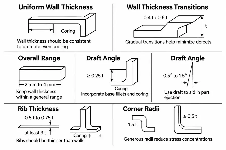
Wall Thickness, Rib, and Draft Design
3) Rib and BOSS Design
Rib thickness can be referenced at 50%–60% of the main wall thickness to reduce local shrinkage and sink marks on the opposite surface caused by overly thick ribs.
BOSS wall thickness can be referenced at no more than 60% of the main wall thickness, with a root fillet of R ≥ 0.5T, to reduce local thick sections and the effect of stress concentration on hole position.
4) Holes, Mating Features, and Geometric Tolerance Design
Precision assembly holes should preferably be molded to minimize the changes in bore size and roundness that could occur due to release of residual stresses during subsequent machining. The dimensional tolerance of ±0.03 to 0.04mm can be taken as a reference value for holes with a diameter < 2mm when the material is suitable and the mould and production process are suitable, and the tolerance should be determined in accordance with the test results.
Calculate coaxiality, flatness, position, and roundness tolerances for material shrinkage, Fiber Orientation, warpage and real assembly requirements. Never directly use geometric tolerances for machined parts.
Keep snap-fit and guide features away from CTF dimensions and areas with strict flatness requirements wherever possible to reduce the effect of local shrinkage and demolding deformation on surrounding dimensions.
5) Gate, Weld Line, and Venting Layout
Draw plan gate sites, CTF dimensions and flow direction. Avoid Weld Lines in critical holes, sealing surfaces or mating areas to minimize the dimensional impact of local stress and shrinkage. For multiple Gates, or materials made from glass-fiber, be careful of the convergence of flow and the Fiber Orientation to avoid the hole-position shift or warpage due to the difference in local shrinkage.
Provide venting at the end of flow. A vent depth of 0.015–0.025 mm can be used as a reference and adjusted according to the material and flash condition to reduce local filling and dimensional variation caused by trapped air.
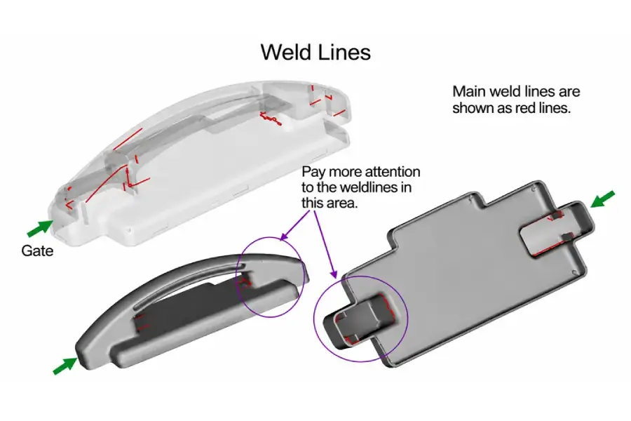
Gate, Weld Line, and Flow Direction
6) Draft, Internal Stress, and Post-Shrinkage
If the Draft Angle is not reasonable, it is difficult to mate accurately. For smooth surfaces use ≥0.5° as a reference and for textured surface ≥1.5°. Do not use sudden changes in wall thickness, do not have corners that are too sharp; be sure to have corner radiuses that minimize stress concentration and dimensional change upon demolding. Take into consideration dimensional changes from post shrinkage or adsorption of water for materials like POM and PA. For the purposes of product requirements, the dimensions of the CTF may be set to inspect the timing and Conditioning state.
6. Advantages and Limitations of Precision Injection Molding
This knowledge of the capability limits of precision injection molding is needed to make early decisions on whether the process is appropriate for the product or not.
1) Main Advantages of Precision Injection Molding
Dimensional stability: Material, mold and process control reduce dimensional variations from batch to batch and are appropriate for products that must be assembled by automated means and have high interchangeability.
Direct molding: Holes, gear teeth and some micro features can be molded directly, which is to reduce the secondary assembly and the subsequent machining.
Environmental adaptability: Some products can have material and structural design that can be adapted to the dimensional requirements of high and low temperature and humidity changes.
Reduction of clearance variance and interference in mass assembly: Critical dimensions and geometric features are well controlled in assembly.
2) Limitations of Precision Injection Molding
Higher initial investment: The mold manufacturing and equipment repeatability, inspection and process control are higher, so the initial investment is generally higher.
Final dimensional stability depends on higher design requirements such as thickness of wall, hole position, tolerances, materials and Gate design. It is necessary that the molding shrinkage and deformation be taken into account in the initial stage of design.
Tighter process window: Tighter stability control is required for temperature, pressure, injection speed, V/P Transfer, Cooling Time and others.
More demands on maintenance: In long-term production, it is necessary to track the wear and tear of the mold and the positioning of the moving mechanism, as well as the dimensions of the critical cavity.
7. What Products Commonly Use Precision Injection Molding?
Precision injection molding is commonly used for plastic parts that require high dimensional consistency, assembly accuracy, or functional fit.
1) Precision Plastic Parts for Medical and Diagnostic Equipment
Commonly used precision components in medical and diagnostic equipment include cartridges, pump components, valve components, connectors, sensor housings and precision locating structures.
2) Precision Plastic Parts for Laboratory and Analytical Instruments
Sample Holders, Fluidic Components, Gears, Guides, Optical Housings, and locating structures are popular components in pipetting, sample handling, optical analysis and automated laboratory equipment.
3) Precision Plastic Parts for Industrial Automation and Sensors
Typically, Sensor Housings, Encoder Components, Connectors, Gears, Guides and internal Actuator structures must interface with a PCB, Metal Insert, Seal, or Bearing.
4) Precision Plastic Parts for Fluid-Control Systems
Bore diameter, coaxiality, sealing surfaces and mating clearances must be controlled for Valve Bodies, Valve Cores, Flow Channels, Pump Components and precision Connectors.
8. Common Dimensional Problems in Precision Injection Molding and Solutions
Based on our years of experience, the following are common dimensional problems in precision injection molding and their causes:
1) Large Batch Variation in Critical Dimensions and Low Cpk
The symptom is that consecutive samples have a large dimensional spread, SPC data varies significantly and dimensions drift after a period of production.
Common causes: Mold or melt temperature changes, unbalanced flow in multi-cavity molds, uneven material drying, uneven wall thickness, and wear at parting surface/inserts.
Solution: The temperature deviation of the mold can be kept at ±1℃ as a reference and the barrel temperature can be calibrated every period of time. If you have a multi-cavity mold: verify runner balance and Cavity dimensions. Dry hygroscopic materials for dehumidifying and control moisture content with drying. Look for parting-surface wear, inserts and abrupt changes in the thickness of the walls as well as local thick sections.
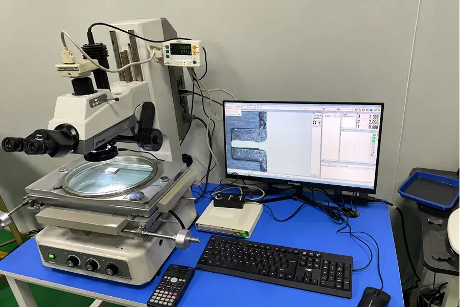
CMM Precision Dimensional Inspection
2) Part Warpage and Flatness Out of Tolerance
Symptom: Large flat surface twists, interferes with assembly and/or parallelism/flatness outside of tolerance.
The main reasons: anisotropic shrinkage of the glass fiber, uneven wall thickness, wrong Gate position, unbalanced cooling circuits, and too high holding pressure.
This is when a solution is required – use Moldflow to check Fiber Orientation and adjust Gate locations. Optimize the thickness of walls and ribs. Use zone-control mold cooling circuit and reduce the difference in temperature between the moving mold and fixed mold halves. It is not recommended to use ≤5°C as an initial control reference for some projects for dimension sensitive products, depending on the material and part structure and warpage validation results. Solve dimensional and warpage problems by adjusting Holding Pressure; consider using a low-warpage modified Grade if needed.
3) Unstable Bore Size, Oversized or Undersized Holes, and Poor Roundness
Symptom: Bore diameter fluctuates or becomes out of round, causing pin fits to be too loose or too tight.
Common causes: A slender Core deflects under melt pressure, holding pressure fluctuates, wall thickness around the hole is uneven, a Weld Line passes through the hole, or the part deforms during demolding.
Solution: Add root support or increase stiffness for a slender Core. Adjust the holding-pressure profile to reduce the effect of excessive holding pressure on the Core. Reduce local thick sections around the hole. Adjust Gate location and flow direction to keep Weld Lines away from critical holes. Also check the draft angle and ejection method.
4) Dimensions Pass After Molding but Change After Storage or Thermal Cycling
Symptom: Dimensions fulfill the requirement right after molding, but after 24 hrs at room temperature or after thermal cycling from −40 to 85°C.
Common causes: Residual-stress release, post-crystallization of semi-crystalline materials, and moisture expansion of PA materials.
Solution: Set up the appropriate Peak holding pressure, Staged holding pressure to minimize residual stress and give adequate Cooling Time. Condition PA parts according to the service environment and measure dimensions in the specified state. Where high/low-temperature or humidity requirements apply, include post-conditioning dimensions in the acceptance criteria.
5) Local Shrinkage Causes Undersized Dimensions
Symptom: Sink Marks occur at BOSSes, thick ribs, or locally thick sections, and the corresponding dimensions become undersized.
Common causes: Local thick walls cause cooling shrinkage, or holding pressure cannot fully reach the thick section before Gate Freeze.
Solution: Reduce material, core out thick areas, or adjust rib/BOSS thickness to reduce local mass. Adjust holding pressure based on Part Weight, residual stress, and post-shrinkage changes. If necessary, adjust Gate location or size to shorten the Flow Length to the thick section and optimize local Cooling.
9. Conclusion
Whether the product can be assembled stable and operate reliably in mass production depends on the definition of the CTF dimension and tolerance in the design, the selection of correct material and mold, and the continuous validation on the product.
Precision injection-molded parts for the medical, laboratory instrumentation, industrial automation and fluid-control markets are engineered and mass-produced at Hollyplasticparts. Helping customers to translate precision designs into stable, manufacturable products, the range of services includes DFM analysis, material/mold solutions, mold trials and mass production quality control. Call us to talk about your precision injection molding project needs.