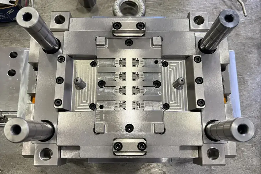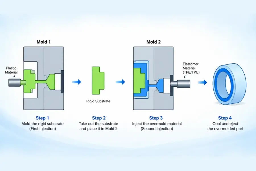
Two-shot molding is a composite manufacturing process which has the composite material compatibility and bonding characteristics, molding position and molding parameters as well as involved. The secret lies in getting a bond of both shots to be a unified part with consistent dimensions and bond.
The engineering characteristics of two-shot molding are introduced in this article, which covers the molding process, material selection, bonding of the interfaces, molding structure design, and common molding defects. It also introduces practical process-control methods used in mass production that can be used to decide the suitability of various products and material combinations to two-shot molding and to enhance molding stability.
1. What Is Two-Shot Molding?
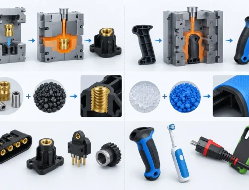
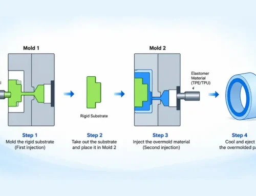
Two-Shot Molding (2K Molding/2-Component Molding): The first material is injected into a molding cycle to make the basic shape, transferred to the second molding position, and then the second material is injected. The finished product is a single piece comprised of two colours, hardness grades or different materials with different characteristics.

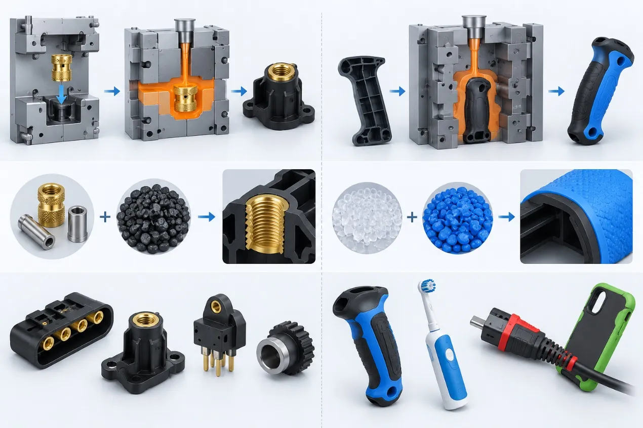
Example of a Finished Two-Shot Molded Part
2. Complete Two-Shot Molding Process
Two-Shot Molding quality depends on the injection parameters of both shots, part transfer, interface condition, cooling, and ejection.
1) First Shot: Molding the Base Section
The main objective of the first shot is to produce a substrate with accurate dimensions, sufficient rigidity, and a clean surface. This provides the foundation for the second-shot molding process and is an important factor in the yield of two-shot parts.
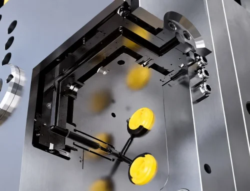
2) How Is the First-Shot Part Transferred to the Second Molding Position?
There are three main types of transfer:
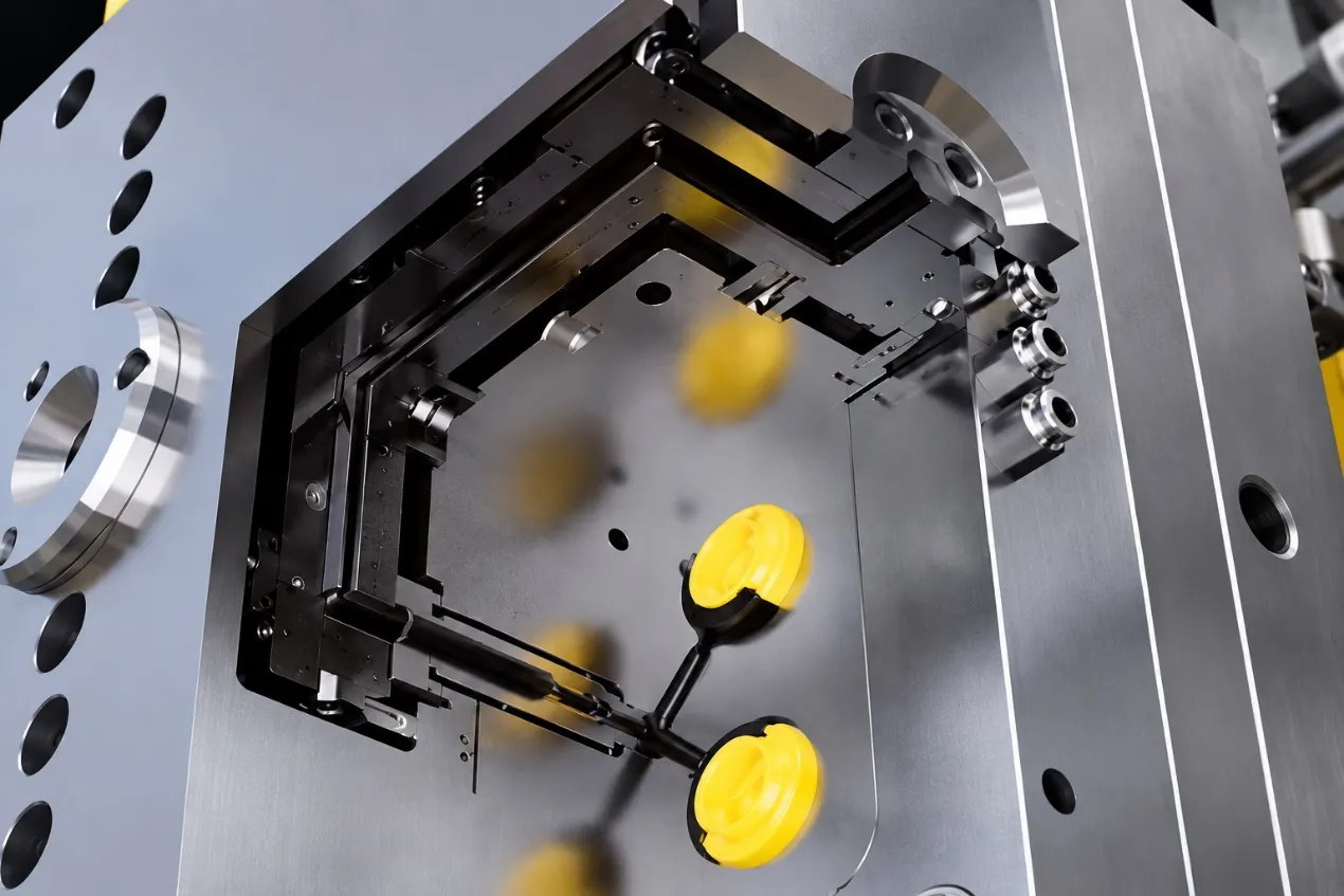
180° rotary table: Most common, for high volume, standard housing, handles. In long production runs eccentricity can occur on the rotary table and result in minor flash or misalignment.
Sliding transfer: High positioning accuracy, suitable for deep overmolding, complicated undercut and appearance parts with high precision. This is a more complex and expensive mould, which is suitable for medium- to high-precision mass production.
Robot insert transfer: the most flexible one, and it is suitable for irregular structures and low-volume customized products. Positioning accuracy is good, however, the interface may be contaminated by manual intervention and lead to inconsistent bonding.
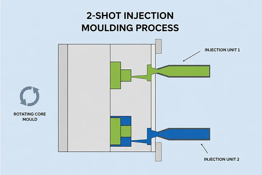
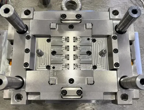
Basic Principle of Two-Shot Injection Molding
3) Second Shot: Molding the Second Material or Color
The second shot is on overmolding, filling, and appearance finishing. Ensure that the temperature of the melt matches both materials in the range of recommended melt temperatures and the interface temperature of the first-shot substrate after it has been transferred should be within the recommended range of first-shot substrate to avoid poor bonding or delamination due to a too-cold interface. A slow-fast-slow injection-speed profile is a good reference: slow injection speed at the start to avoid melt impact which could result in shifting of the substrate, fast injection speed in the middle stage for full filling, then a slow injection speed at the end to vent and stabilize injection pressure.
4) Cooling, Mold Opening, and Ejection
Do two-shot parts with separate, differentiated cooling. Cool down the rigid first-shot substrate a bit faster than second-shot soft material, which should result in the product setting while not shrinking too fast to create sink marks or bubbles in the soft material.
Use an even opening and ejection force on the mold. Remove material from hard portions of the substrate first and then not load the two-material interface directly since it may be ripped apart before it hardens.
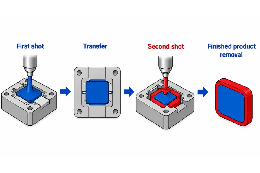
Two-Shot Injection Molding Process Flow
3. What Materials Can Be Used for Two-Shot Molding?
The key to material selection is to make an overall judgement on the compatibility of the two materials for the purpose of interfacial bonding, thermal characteristics and molding properties.
1) What Factors Should Be Considered for Two-Shot Material Combinations?
There are two types of bonding: chemical molecular bonding and mechanical interlocking. If materials are compatible, molecular interdiffusion is possible; otherwise, there should be material mechanical locking features.
Shrinkage difference: Shrinkage difference can be used as material screening early reference. You should first test combinations that have smaller shrinkage differences as they are similar to the ones in this project. If two combinations have significantly different shrinkage characteristics, ensure mass production viability by mold trials, dimensional testing and thermal cycling.
Thermal compatibility: The melting temperatures and coefficients of thermal expansion of the two materials need to be compatible. Too big temperature variations can cause stress in the mold that is not equal and cause cracking or debonding after thermal-cycle testing.
Process compatibility: Hygroscopic materials like PC, PA66 or TPU need special drying equipment. Too much moisture results in bubbles and poor bonding.
2) Common Two-Shot Material Combinations
The following combinations of materials are preliminary and should only be used in a first selection:
ABS+TPU: Moderate bond strength; often use in consumer-electronics housings and handheld parts, mechanical interlocking is required for reinforcement.
PC+TPU: Highly locked, excellent high/low temperature performance; widely used in power tools and precision-instrument handles.
PA66+TPV/TPU: Excellent bonding, wear and weather resistance; applicable to the interior parts of automobiles, weather-resistant parts of outdoor tools; drying or removing moisture is a strict requirement.
PP+TPE: Bonding is determined by the type of TPE to be used. TPE developed for PP can provide good bonding, some general purpose TPE grades need mechanical interlocking.
Same substrate in different colors (ABS+ABS, PC+PC): Strong bonding, a wider process window, and high yield; suitable for two-color decorative appearance parts.
3) How Do Two Materials Form a Reliable Bond?
Molecular chemical bonding: Maintain the appropriate interface temperature for the first shot. The hot second shot melt penetrates the surface of a substrate and diffuses and entangles the molecular chains. Cooling creates an integrated connection.
Mechanical interlock reinforcement: Under-cut, through-hole, or grooves are added to the bonding surface, and the size is 0.5–1.2 mm and the draft angle is 2-3°. Despite the absence of chemical bonding, the physical interlock may still help to prevent delamination.
For increasing the interfacial friction, interface process optimization is recommended, namely a textured bonding surface roughness of Ra 3.2-6.3 μm.
4. What Should Be Considered in Two-Shot Product Design?
The structural design of a Two-Shot product needs to account for the first-shot molding stage, second-shot overmolding, and final demolding.
1) Wall Thickness Design
For the first shot substrate, a reference thickness of 1.2–2.5 mm can be used, with a local minimum of 0.8 mm. The wall will be too thin if the second shot melt pressure is too high; the wall will be too thick if the second shot melt pressure is too low, cooling time will be too long, resulting in low interface temperature and affecting bonding.
The recommended wall thickness for the second-shot overmold (soft material) is 1.5–3.0 mm, with local thick sections kept within about 4 mm. Excessive thickness can cause sink marks and bubbles.
2) Shut-Off Design to Control Flash
Poor Shut-Off fit can allow the soft material to leak and create flash along the boundary.
A Shut-Off step or flash-relief feature can be added at the material boundary, with reference dimensions of 1.5–2.0 mm deep and 0.8–1.0 mm wide. In some TPE Overmolding designs, a Shut-Off interference of approximately 0.076–0.127 mm can compensate for first-shot shrinkage and manufacturing tolerances.
Use a draft angle of about 3–5° at Shut-Off areas and along longer demolding surfaces, increasing the draft for deeper textures. If the draft is too small, first-shot shrinkage may create a gap at the mold Shut-Off, allowing second-shot melt to enter and form flash.
3) Gate, Venting, and Appearance Planning
Place the first-shot Gate on a non-cosmetic surface where possible. Keep the second-shot Gate away from the material-bonding interface to reduce local bonding defects caused by high-speed melt washing across the substrate surface.
Provide a vent groove at the end of second-shot filling, with a reference depth of 0.02–0.03 mm and width of 3–5 mm. Because the first-shot substrate obstructs flow inside a two-shot part, air is more likely to become trapped at the flow end and overmold corners.
Keep the material boundary away from high-gloss cosmetic surfaces where possible, and plan bond lines, weld lines, and Gate marks in non-visible areas.
5. Advantages and Limitations of Two-Shot Molding
Two-Shot Molding can integrate multiple materials or functions into a single part.
1) Advantages of Two-Shot Molding
Reduces secondary overmoulding, assembly and adhesive dispensing operations, leading to lower cost and increased efficiency.
Enhanced quality: Integrated in-mold forming ensures enhanced interface bonding and eliminates manual assembly tolerances. The resulting components have superior sealing, slip resistance and aging characteristics compared to the assembled components.
Integrated structure: Allows combined functions of rigid support and flexible protection, two-color appearance zoning and integrated sealing function.
Consistent appearance: Material edges are clean, well controlled, adhesive spills from post processing are minimized.
2) Limitations of Two-Shot Molding
Expensive up-front expenses: Two-shot molds are more expensive than single-shot molds and a dedicated two-shot machine will be more costly. The process is well adapted to high annual production volumes and very uneconomical for small volumes.
High technical requirements: product design, material matching, mold accuracy, process setup and so on, must have high requirements for control. Defects are not tolerated and experienced engineering is needed to make a successful product.
Material restrictions: Incompatible material combinations need special mechanical features and certain special engineering plastics and highly flame-retardant materials are not easy to process reliably in the mass production of two-shot processes.
High maintenance cost – Rotary tables, slides, and dual-shot cavity structures are more complicated than single-shot molds and require more expensive maintenance and replacement parts.
6. What Products Are Suitable for Two-Shot Molding?
The following product categories can make effective use of the process value of integrated two-shot molding:
1) Soft-Touch and Anti-Slip Parts
Handles for power tools, appliance controls and handheld-instrument enclosures. A rigid plastic (PC/ABS) and a soft material (TPU/TPV) offer both structural rigidity and anti-slip grip and vibration-damping feel.
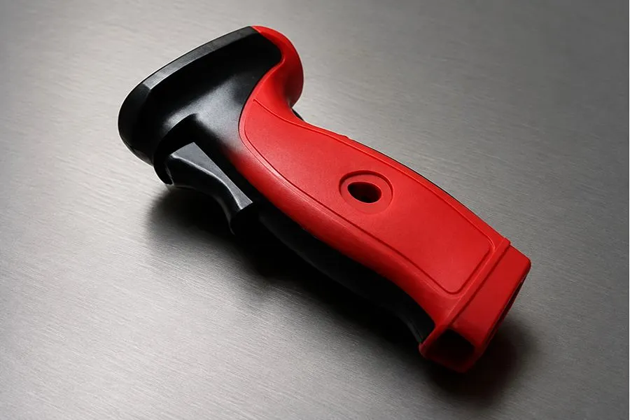
Two-Color Power-Tool Handle
2) Integrated Sealing Parts
Waterproof connectors, sealed small appliance and automotive dust-protection parts. The integrated and two-shot molding process avoids assembly gaps, ensures higher sealing precision and minimizes joints and assembly errors in conventional assembled structures.
3) Two-Color Appearance and Functional Identification Parts
Consumer-electronics housings, appliance decorative panels and key component function-zoned parts. Different colored integrated molding provides visual layering and functional zoning.
4) Rigid + Flexible Functional Parts
Handles on medical devices, car interior protective parts and wearable-device cases. The rigid substrate offers the accuracy of assembly and structural strength, while the flexible overmold offers impact protection, anti-slip performance and a skin friendly feel.
5) What Products Are Not Suitable for Two-Shot Molding?
Very poor economics generally occur for low volume custom products (annual volume <30,000 pcs); the investment in the mold and equipment is more than the cost savings in the process. Consider insert molding or assembly.
Parts with ultra-high precision and ultra-thin parts (wall thickness <0.8 mm): The dimensional stability is hard to achieve due to the lack of rigidity of the first-shot substrate and the deformation caused by the second-shot melt pressure.
Special products for highly corrosive or extreme service: Most common two-shot material combinations don’t offer enough weather or chemical resistance and can age and delaminate at the interface.
Products containing very high shrinkage variation, such as PP + silicone: The shrinkage mismatch is high, shape and performance is not easy to control consistently with the use of conventional mold and process, mass production yield is low.
7. Common Two-Shot Molding Problems and Troubleshooting
Based on years of Two-Shot Molding project experience, HollyPlasticParts has summarized several common molding problems and the corresponding troubleshooting approaches below.
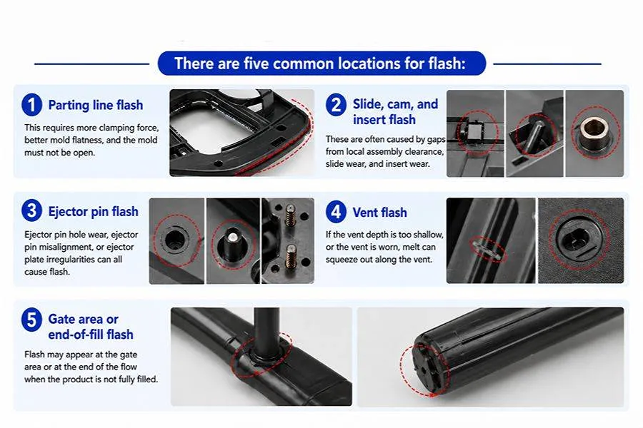
Example of Flash Defects in Two-Shot Injection Molding
1) Interface Delamination, Peeling, or Insufficient Bond Strength
The symptom is that the second shot material peels off from the first shot surface readily, debonds during thermal cycling or has weak bonding in the local areas.
Common causes: Two material grades are incompatible; mold release agent, oil or dust at the bonding surface; too cold at the interface during the second shot; mechanical interlocking is not sufficient; or air trapped at the bonding interface.
Troubleshooting: Ensure bonding compatibility of the specific material grades; keep the first shot cooling time short or change the transfer cycle to avoid overcooling the bonding area; clean the bonding area and reduce any mold release agent contamination; incorporate Mechanical Interlock features at bonding areas where bond and peel loads are not adequate, such as undercut or through hole; incorporate and/or optimize venting at areas of poor bonding/peeling.
2) Second-Shot Overflow or Flash
Symptom: The second shot material is running along the material boundary or Shut-Off area of the device and creating flash.
Common causes are: Excessive Shut-Off clearance, shrinkage or warpage and the first shot is no longer fitting into the second cavity; rotary table offset or core offset; insufficient clamping force; or high second-shot Injection Pressure or Injection Speed.
Troubleshooting: Measure the actual dimensions and warpage of the first shot before the second shot; inspect and rework the Shut-Off contact surfaces; calibrate the rotary table, core and other positioning mechanisms; check the clamping condition; after confirming the proper mold fit, adjust the second-shot V/P Transfer, Injection Pressure and Injection Speed.
3) Color Misalignment or Unstable Material Boundary Position
Symptom: A transition area between two materials moves or an area of transition moves and/or changes from one molding cycle to another.
Common causes: unstable positioning of first shot in second cavity; repeat-positioning error in rotary mechanism; melt impact on first shot during second shot filling; inadequate local rigidity on first shot; fluctuations in fill during second shot.
Troubleshooting: Calibrate rotary mechanism, locate pins, Core, stops, positioning features; add local support or reinforce the weak areas of first shot that are needed; optimize Gate direction, reduce the influence of direct melt on the positioning area; optimize the initial second shot Injection Speed, improve the consistency of the boundary position.
4) Part Warpage or Dimensional Deviation
Symptom: The molded part is bent, out of tolerance or interference will happen when assembled.
Common causes: Overmold with different shrinkage characteristics on one side of the piece, or local shrinkage differences between the two shots; lack of rigidity in the first shot; cooling differences between the two shots; or incorrect packing parameters.
Troubleshooting: Compare the actual Mold Shrinkage of both materials; Optimize second-shot overmold thickness and symmetry of structural design; Optimize the rigidity of first-shot by adding ribs and local structural changes; Inspect the Core/Cavity, cooling channels at both stations, and the distribution of mold temperature; Adjust the second-shot Packing Pressure and Holding Time in accordance with the change of dimensions;
5) Air Traps, Bubbles, or Burn Marks in the Second Shot
The symptom is burn marks, black spots or bubbles on the second-shot surface or weak bonding at the material interface locally.
Possible reasons: There is not enough venting at the Flow Front end or convergence area; the Gate and Flow Path form an air-trap zone; end-stage Injection Speed is too high; or hygroscopic materials like TPU and PA are not dried enough.
Troubleshooting: Ensure venting is at the Flow End, holes, Bosses, overmold corners, and flow-convergence areas; add or clean Vents as needed; adjust the Gate and Flow Path to allow the air to flow smoothly; reduce the end-stage Injection Speed accordingly; control drying conditions based on the specific material grade.
6) Second-Shot Short Shot
Symptom: The second shot does not completely fill, leaving a large amount of material away from the Gate, in thin wall sections or at the Flow End.
Excessive Flow Length, walls that are locally thin, Gate size or position, insufficient venting, insufficient material flowability or insufficient Melt Temperature, Injection Speed or Injection Pressure.
Troubleshooting: Investigate the effect of Short Shot location on Gate and Flow length and local wall thickness; optimize Gate size and position and reduce flow length as required; optimize the end-of-fill venting; optimize Melt Temperature, Injection Speed and Injection Pressure within the material processing window.
8. Conclusion
Two-Shot Molding combines structural, functional and aesthetic attributes in one molding process. When the material used is mature, production volume is stable, and there are high integration requirements, two-shot molding can give better mass production efficiency.
The integrated manufacturing support that HollyPlasticParts offers customers starts with material matching and ends with product-structure optimization, followed by the creation of two-shot mold and mass production of the Two-Shot Molding. Based on the function of the product, material combination, and volume needs, we will formulate the appropriate molding solutions and assist in solving the engineering problems that need to be addressed, such as interfacial bonding, dimensional stability and consistency in mass production. Call us to talk about your Two-Shot Molding project needs.