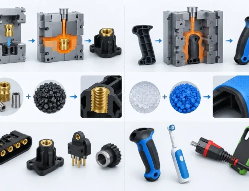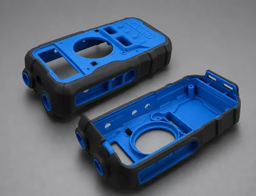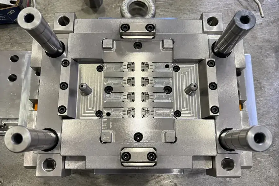
The problem with achieving the structural strength, tactile feel, slip resistance, sealing and durability performance is nearly impossible using single material injection molding. The overmoulding process involves joining two or more materials together to give a single molded part to products that require more than one part to meet the functional requirements.
The general concepts, process flow, materials and design considerations of overmolding will be discussed. It refers to all combinations of materials and their use, to some typical production issues such as bond failure, deformation, incomplete bond filling and dimensional deviation, and reviews the important control parameters to be considered for product development and mass production.
1. What Is Overmolding?
Overmolding combines different materials to achieve functions that a single material cannot provide.
1) How Overmolding Works
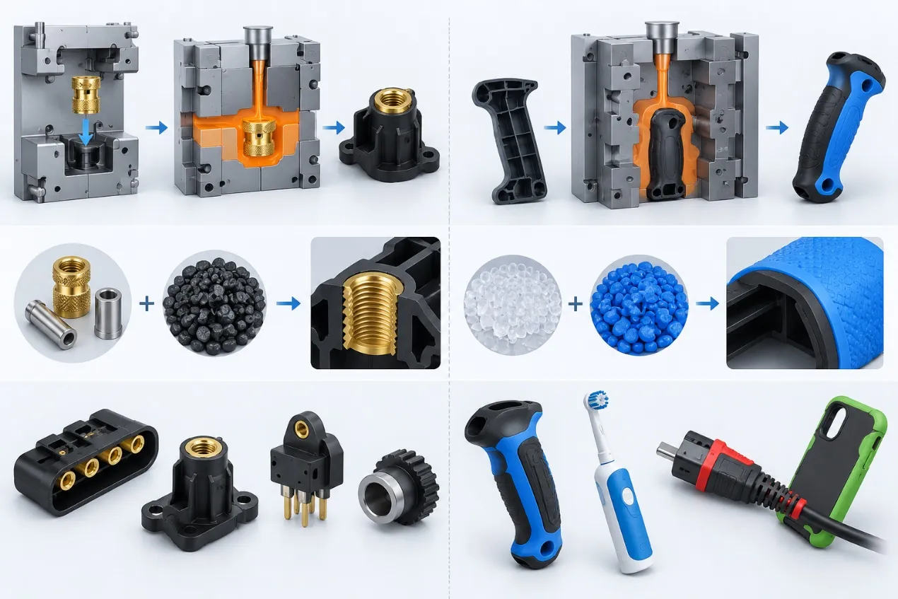
A molding technique that involves molding a layer of plastic or elastomer onto a molded and/or formed pre-made substrate, resulting in a molded part composed of molded elastomer and molded plastic. This is called Rigid Substrate + Soft Overmold = Integrated Part.
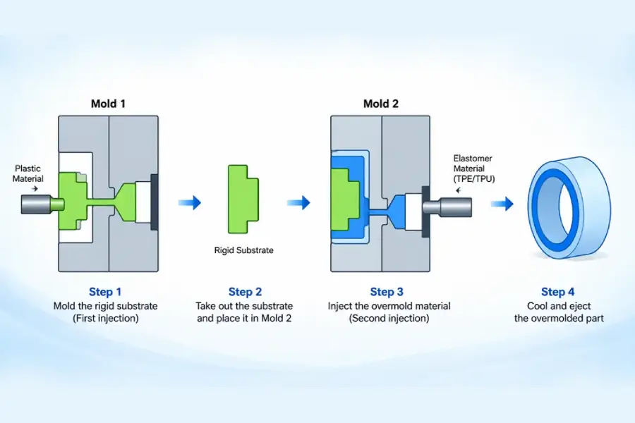
Basic Principle of Overmolding
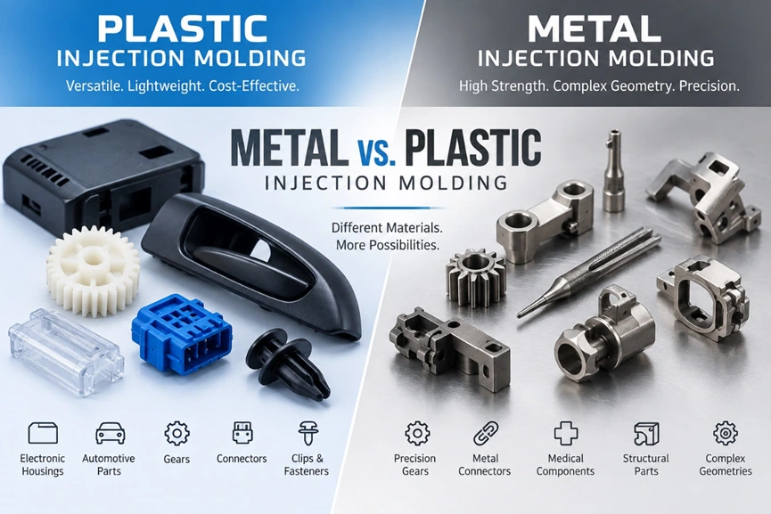
2) Difference Between Overmolding and Conventional Injection Molding
a.Different molding process: Usually a single material is used for a single molding process in conventional injection molding. Overmolding is comprised of substrate molding and a second overmolding, thus both materials need to be considered with respect to their temperature, shrinkage and cooling properties.
b. Different functions for the products: Overmolding can be used to embed an integral, functional area (e.g., slip-resistant, cushioning, sealing or insulating) into a rigid product.
c. Other material selection – Generally, conventional single material molding is based on the molding properties of molding material itself. Overmolding needs to confirm that the substrate and overmold material is compatible to bond together.
d. Differential dimensional control: Second injection process with heat and pressure on the substrate. The final dimensions are influenced by substrate rigidity, the positioning of the substrate, and the difference in shrinkage between the two materials.
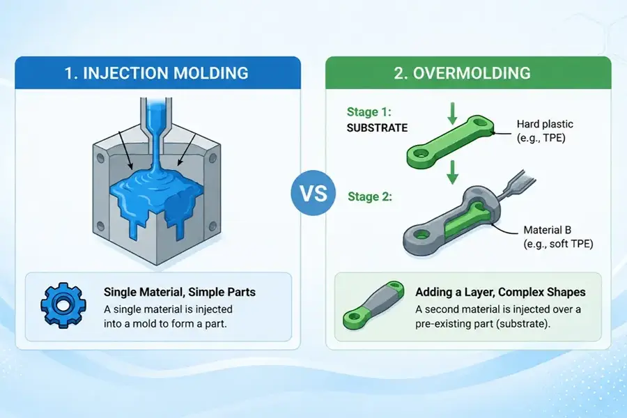
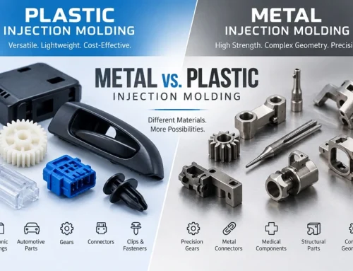
Conventional Injection Molding vs. Overmolding Process Comparison
2. Advantages and Limitations of Overmolding
Understanding its advantages and limitations helps determine whether the process is suitable for a specific project.
1) Main Advantages of Overmolding
a.The secondary parts like soft rubber, anti-slip layer, sealing parts and other parts could be molded separately and directly attached to the main part, which leads to just a few parts to be dispensed, bonded and assembled.
b. Integrated functions: Rigid parts (structural elements), soft functional parts can be combined together, e.g. rigid plastic structure (support) + soft (anti-slip). Or with a stiff shell and sealing and insulating function.
c. Less need for component parts: Sealing gaskets, soft sleeves or cushioning parts which would normally need to be installed separately can be built into the main part.
d. Functional structures: It can be used on products, which have more than one functional structure such as slip resistance, cushion, sealing, insulation, flexible area in a certain place.
2) Limitations of Overmolding
a.Restricted material compatibility: Bonding properties are different from different grade combinations of substrate and overmold materials, requiring compatibility between the materials to be confirmed. Mechanical interlocks can be used to reinforce bonding if it is inadequate.
b. Thin wall or low rigidity substrates can shift or deform under the melt temperature and pressure due to risk of second deformation during second injection.
c. More complex mold structure: In order to produce the secondary overmold, it requires positioning of the substrate, shut-off, overmold cavity features, etc. in the secondary overmold tool. In the two-stage molding, the substrate transfer and loading is also needed.
d. Other process variables such as the melt temperature, mold temperature, shrinkage and flow characteristics of both materials influence the final overmolding result.
3. Overmolding Process
Overmolding includes substrate producing, positioning, secondary molding and inspection. The effect of each stage is on the final bonding performance and the final stability of the product. The full process provides the ability to alert on potential production controls early.
1) First Injection: Substrate Molding and Pretreatment
The first injection is the substrate. Once demoulded, check dimensions, surface finish and remove flash and burrs. Clean the surface of the overmold before the second molding operation to avoid any oil, mold release agent and dust on the substrate surface which may influence the secondary bonding.
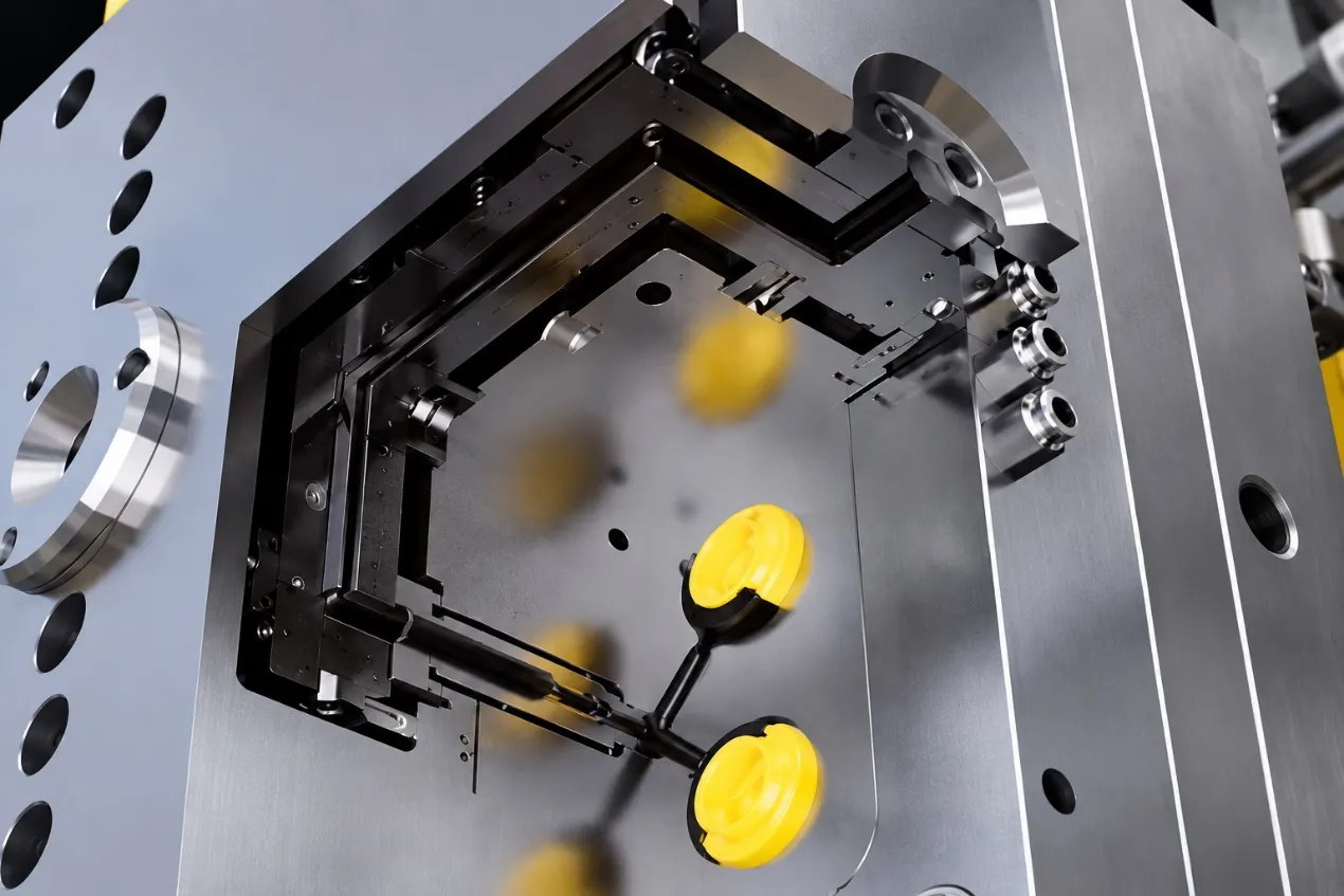
2) Substrate Positioning and Secondary Mold Closing
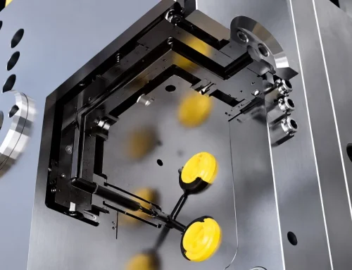
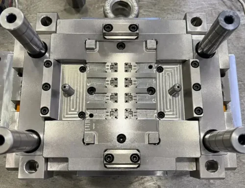
Install the substrate into the secondary overmold tool, and use profile stops, locating posts, clearance slots, etc. to position it. For reference, maintain positioning clearance of 0.015 mm to prevent damage to the clamping, misalignment or the shift of the substrate during the second injection.
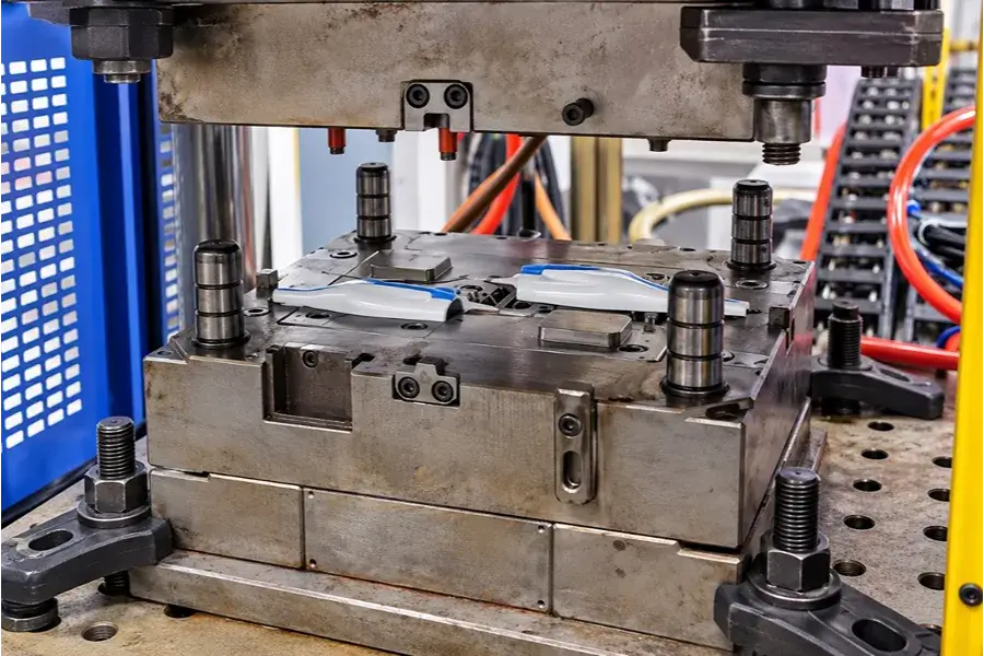
Overmolding Tool Positioning and Secondary Mold Closing
3) Second Injection: Forming the Overmold Layer
After the 2nd substrate is placed, give the 2nd injection. The overmold material (such as TPE or TPU) is extruded on top of the substrate and into the overmold area. Modify injection pressure and speed to assure full penetration without compromising the substrate. The major control of overmold shrinkage is held by holding pressure.Overmold shrinkage and the final molding condition is primarily controlled by the holding pressure.
4) Cooling, Demolding, and Quality Inspection
Following the 2nd injection, cool, open the mold and eject. Check the flash, overmold coverage, hard/soft material boundary, deformation and surface condition as well as incomplete filling. Peel, tensile or bend tests can be conducted for those applications which need to check the bond strength. Automotive, medical or other products may require high/low temperature testing, water proof or air-tightness testing depending on the service requirements.
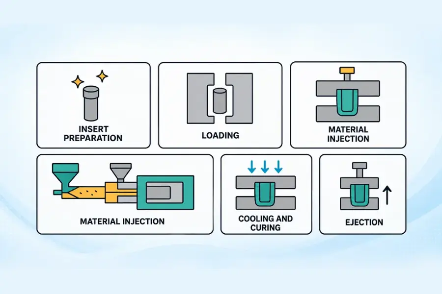
Overmolding Process Flow
4. Common Overmolding Materials
Materials, as well as plastics and elastomers, have different bonding properties that are crucial for successful overmolding. Proper substrate and over molding material are essential for product performance and reliability.
1) Common Substrate Materials
ABS / PC-ABS: Very good shape retention and processability properties; most often employed in consumer electronics, appliance casings and handheld products.
PC (Polycarbonate): High strength and impact resistance, can be used in the case of equipment, medical devices, etc. that require higher structural strength.
PA6 / PA66 (Nylon): Good mechanical properties and wear resistance are available for making industrial parts, such as automotive parts, power tools and structural parts.
PBT and Glass-Fiber-Reinforced PBT: Suitable for structural parts for industry and electrical applications that require stiffness and dimensional stability.
PP (Polypropylene): Light weight and resistant to chemicals.
2) Common Overmold Materials
They are commonly used for soft-touch, anti-slip and cushioning applications as well as in some sealing applications (TPE / TPR (Thermoplastic Elastomer)) Select hardness for grip, deformation and need.
TPU (Thermoplastic Polyurethane): Good wear resistance, elasticity, can be used for overmolded structure, such as tools, automotive parts and outdoor equipment.
Liquid Silicone Rubber (LSR): Use for materials that are needed to have higher heat resistance, higher elasticity or special biocompatibility. A new moulding machine and tool design, which is different to traditional thermoplastic over moulding.
Rigid-to-rigid overmoulding can also be used with rigid materials (ABS / PC) for colour separation, appearance features or where limited geographically for structural purposes.
3) Compatibility Between Different Materials
This bonding performance is quite different for a substrate material and an overmold material. There are general combinations of materials that are grouped together:
Good compatibility: ABS + SEBS-TPE, PC + TPU, and PA + TPU. These combinations can result in a good bonding interface by molecular diffusion and chemical bonding between the materials.
Conditional compatibility: PP + modified dedicated TPE. The typical TPE grade used for PP overmolding is one that has been specifically developed for PP.
Poor compatibility: PP + general purpose TPE and POM + some soft materials. Weak combinations for direct bonding, mechanical interlocks—via through-holes, undercuts, or grooves are recommended.
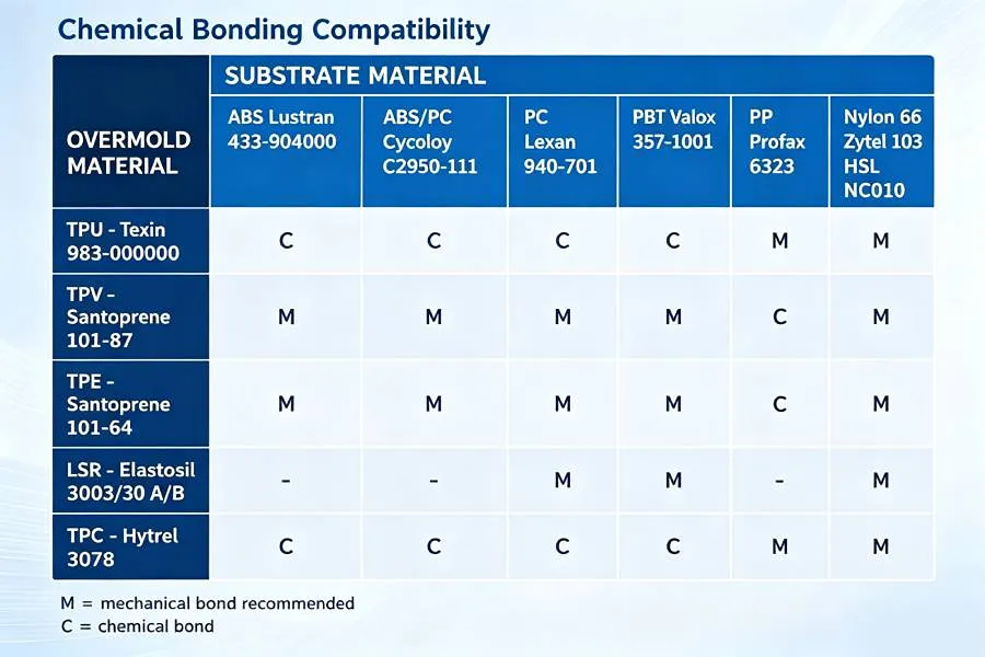
Common Overmolding Material Combinations / Material Compatibility Chart
5. Key Design Points for Overmolding
Depending on materials, equipment and product structure the final overmoulded product will be determined. The risk of defect can be minimized with appropriate wall thickness, bonding characteristics and mold fit.
1) Dual-Layer Wall Thickness Design
For comparison, the soft overmold layer can be 40%-60% of the thickness of the substrate. There are about 0.8 mm of minimum effective overmold thickness and 1.0-2.5 mm of functional soft-material thickness. Maintain as flat as possible an overmold layer and control the overmold thickness to within 15% locally for reference (unless more is needed, due to material buildup).
2) Mechanical Interlock Design at the Bonding Interface
Use a Mechanical Interlock when chemical bonding is inadequate, or the overmolded surface has a high peel load. Common features are grooves or surface textures, wraps around edges, through holes and undercuts, and segmented retention grooves for long overmoulded areas. Use mechanical locking elements over-moulded at the edges and at mains load points to provide peel and displacement resistance.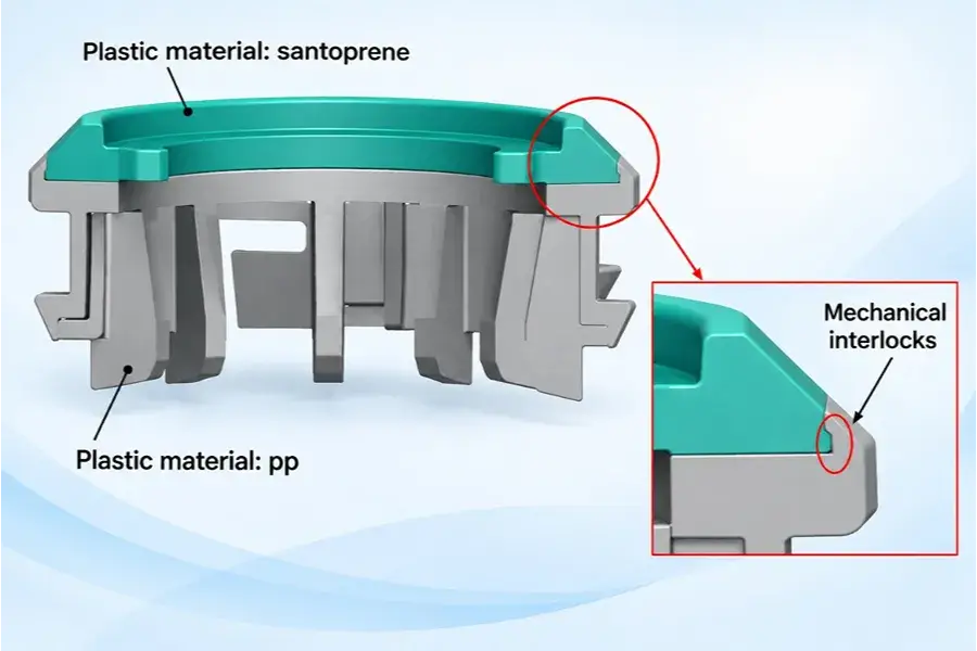
Mechanical Interlock Design at the Bonding Interface
3) Gate and Runner Layout Design
The Gate should have as little Flow Length as possible in the Overmold material and the unsupported Thin Wall Substrate areas should be avoided. Where overmolded areas are large, use side gates, fan gates or multiple gates depending on the flow path. Make effective venting at Flow End to minimize incomplete filling and entrapped air due to thin layer, long distance flow.
4) Positioning and Shut-Off Surface Design
Ensure secondary mold stable positioning areas on the substrate as well as account for the actual dimensional tolerance after the first injection. When the substrate is not over molded, a Shut-Off Surface must be provided; otherwise, Flash may occur, or there may be interference with the mold closing or crushing the substrate due to too tight a fit.
5) Cooling and Shrinkage Control
When pulling forces on the substrate are not balanced during the shrinkage of the second material, large one-sided overmold areas, local thick sections or unequal overmold distribution can cause this. Take shrinkage properties of material and control warpage into consideration while designing the product, such as overmold distribution, cooling-channel location and local cooling.
6. Common Applications of Overmolding
Overmolding is suitable for consumer electronics, such as TWS earbud housings, remote-control buttons, smart-home panels and anti-slip areas on handheld devices.
Automotive components: Armrests, control components, wire-harness sealing boots, buttons and cushioning structures are examples of automotive components that can be overmolded.
Medical device elements: Medical device handles, housings, buttons and some sealing structures may be a combination of rigid plastics and soft overmold.
Overmolded industrial equipment and tools: Power-tool handles, industrial inspection-instrument housings, equipment knobs and outdoor protective components are typical overmolding applications.
7. Common Overmolding Problems and Solutions
From years of overmolding project experience, HollyPlasticParts summarized some problems and the troubleshooting solution, as follows:
1) Overmold Peeling or Bond Failure
Symptom: Overmold layer can be pulled off of the substrate, or the edge will lift or peel strength will be inadequate.
Common causes: Material grades that are incompatible; oil or mold-release contamination on bonding surface; insufficient secondary molding temperatures; or insufficient filling of the bonding surface.
Troubleshooting: Make sure that the specific Substrate Grade is compatible with the Overmold Grade, and then check the failure surface after peeling. If the whole layer comes apart easily, pay attention to the compatibility of the materials and surface condition. If the bonding is just not enough in the local areas, then concentrate on the melt temperature, mold temperature, and the real filling condition.
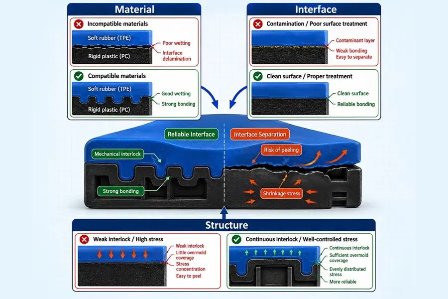
Overmold Peeling
2) Deformation or Dimensional Out-of-Tolerance After Overmolding
The dimensional tolerance of the substrate is achieved after the initial molding, but after Overmolding, the warpage, flatness deviation, or assembly dimensions are out of tolerance.
Common Causes: Difference in shrinkage of the two materials, difference in shrinkage from one side on the over molding, deformation of the material during the second injection, or unstable substrate position.
Troubleshooting data: Dimension – after first molding, after second molding and after cooling. When the part has already been distorted at the time of demolding, attention needs to be paid to secondary pressure, temperature and positioning. If the deformation will keep increasing in cooling, keep in mind material shrinkage difference and overmold distribution.
3) Incomplete Overmold Filling or Short Shot
Caution: It is necessary to ensure that the designed area is completely covered by the overmold material, which is usually found at the Flow End, corners, grooves or away from the Gate.
Common causes are too long flow length, too localized a thin overmold area, too little venting or insufficient actual filling capacity.
Troubleshooting: Take a Short-Shot study to see the Flow Front. When the flow becomes stalled at the same point each time, concentrate on the flow path, the thickness of local material and venting. When the condition of the incomplete fill is not consistent, check the temperature difference of the melt, injection speed and injection pressure.
4) Flash or Material Overflow
Symptom: Soft material goes beyond the overmold line into areas not required by the design.
Common causes: Substrate dimensional variation, Excessive Shut-Off clearance, Worn shut-off surfaces, Abnormal mold closing and Excessive local Cavity Pressure.
Troubleshooting: If Flash keeps showing up at one spot, the first thing is to check the substrate dimension and the related Shut-Off Surface. If it shows up at several locations simultaneously, inspect mold closing and secondary injection pressure as well as rule out mold-fit as the cause of the problem.
5) Stress Cracking at the Hard/Soft Material Interface
Failure mechanism: Bonding of the two materials, but crack formation along the hard/soft interface edge. In a few products the cracking only occurs after a storage time.
Causes: Residual stress at the edge of the interface, a large shrinkage difference between materials, or a sharp corner or sudden change in section at the interface.
Troubleshooting: When cracking starts to happen right after demolding, attention should be given to interface geometry and molding stress. If the cracks open up slowly after a few hours or days, consider shrinkage difference and residual stress and design fillets, thickness transitions or material combinations accordingly, depending on the origin of the crack.
8. Summary
The essence of overmolding is to integrate two materials and then with effective material matching and structural design, realize the product functions and give it manufacturing efficiency. From material selection, structural optimization, mold design to mass production’s validation, HollyPlasticParts has a long track record of supporting project development, which reduces the development risk, and enhances product reliability. Whether it is hard/soft integration, anti-slip cushioning, sealing protection or complicated functional integration, please contact us for professional solutions.