If the product has simple geometry, a uniform wall thickness and the tolerances are standard, then in most cases, a basic DFM check is appropriate. A full DFM Review is highly recommended prior to mold manufacturing, however, for products that are complex in structure, require expensive tooling or pose high production risk, it is highly recommended.
Before mold manufacturing begins, some injection molding risks may already be present in the product design. Sink marks, warpage, difficult ejection, flash, short shots, and unstable dimensions are not always caused by the molding process alone. They may also be related to the product structure, material selection, or mold design, and may go unnoticed if these aspects are not reviewed early enough.
Based on Holly Plastic Parts’ experience in mold design, trial molding, and mass production, a professional DFM review should cover more than checking design rules one by one. It should evaluate whether the product structure, material selection, mold strategy, and production requirements can work together in actual manufacturing. This helps identify potential problems while they can still be corrected, before tooling investment and production costs increase.
1. What Is DFM in Injection Molding
DFM (Design for Manufacturability) is not a set of product design rules, but rather a design review prior to the manufacture of the mold. It is not to gauge conformance to individual design guidelines, but to determine whether the product can be produced in reasonable amounts at a reasonable cost, with reasonable processing stability, and at a controllable risk by a process of mold fabrication, trial molding, and mass production.
A DFM Review is usually performed after the product design is complete, prior to the start of mold design. It is possible to change the structure of the product at this time. The engineers analyze the product systematically from geometry, material properties, mold manufacturing ability and production requirements, and give specific engineering recommendations to decrease the manufacturing risk.
2. Which Projects Require a Complete DFM Review
If the product has simple geometry, a uniform wall thickness and the tolerances are standard, then in most cases, a basic DFM check is appropriate. A full DFM Review is highly recommended prior to mold manufacturing, however, for products that are complex in structure, require expensive tooling or pose high production risk, it is highly recommended.
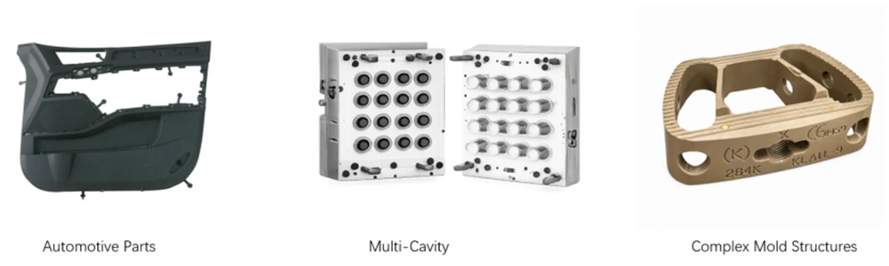
Projects Requiring Complete DFM Review
- New Product or First-Time Tooling Projects: In the case of a new product, you will not have experience to refer to; no trial molding data and no prior engineering experience. All the structural features and processing parameters should be checked for the very first time.
- Multiple side actions are usually necessary for complex mold structures, such as those with side holes, undercuts, deep snap-fits, or complex internal structures. These structures are at great risk of shut-off failure, interference and demolding, flash, and short shots.
- High Precision Products: Precision components that have multiple mating dimensions and tolerances of ±0.05 mm or tighter are very sensitive to dimensional variation and may not fit together easily.
- High Cosmetic Requirement Products: Parts made with high gloss, transparent, painted, platted, and textured parts are very sensitive to cosmetic defects, including sink marks, weld lines, gas marks, color variation and ejector marks. Hence, appearance risks need to be carefully considered at the DFM stage.
- Automotive Parts:Structural parts, functional parts, exterior trim, interior trim. The warpage, deformation, dimension, weatherability of these products has to be strictly controlled, and the most important requirement is the stability of production.
- Multi-Cavity and High-Volume Production Projects: The consistency of the parts produced and the uniformity of the cooling process in cavity-to-cavity filling all have a direct effect on the yield of the molding. Production risks are much greater for these multi-cavity and high-volume molding projects, such as 8, 16, 32, and greater cavity molds.
3. What Does a Professional DFM Review Actually Check?
A DFM Review is not just an itemized list of Draft, Wall Thickness, Rib and other design rules. Rather, it is the product development process that is used to carefully consider product needs, mold strategy, part geometry, material suitability, and production potential.
The engineering decisions made in each review stage are directly affected by the previous review stage. So, for experienced engineers, the review is usually carried out in a standardised fashion.
1)Confirm Product Requirements
To verify product requirements is the first step since it is the material, tolerance and cosmetic requirements that determine the engineering criteria across the entire DFM review.
- Material: final material grade, shrinkage rate and flowability.
- Critical Dimensions: Dimensions and tolerances that are critical to function.
- Appearance: Class A/Class B surfaces & cosmetic requirements.
- Surface Finish: SPI, VDI and texture requirements.
- Assembly: Screws, snap-fits and ultrasonic welding.
- Production Volume: The annual production volume and mold life requirement.
Review Output
- Whether the product design input is complete.
- Whether the project is ready to enter the DFM stage.
- Whether additional technical information is required.
Engineering Review Focus
As part of our experience, we have found that one of the most frequent causes of multiple DFM revisions is when the material grade is altered after the structural review has already occurred. After material change, shrinkage, gate design, steel-safe allowance and Moldflow conclusions are frequently re-evaluated.
2)Define Mold Opening Direction
Once the mold opening direction is established, the engineer can accurately evaluate the draft angle, parting line, and required side actions.
- Mold Opening Direction: Primary mold opening direction.
- Parting Line: Parting line location.
- Undercut: Presence of undercuts.
- Slider / Lifter: Whether side actions are required.
- Shut-off: Reliability of shut-off surfaces.
Review Output
- Recommended mold opening direction.
- Whether Sliders or Lifters are required.
- Preliminary parting line proposal.
Engineering Review Focus
The first rule of DFM is that it always minimizes the number of side actions without impacting product function or assembly. Additional Sliders or Lifters will add mold cost, machining time and assembly time, maintenance time, and tooling risk over the years.
3)Review Part Geometry
Part geometry defines melt filling, packing, cooling and part ejection and is the fundamental review point of a DFM analysis.
- Wall Thickness: Thickness variation, thick sections, and hot spots.
- Draft: Draft direction and angle.
- Rib: Thickness, height, and spacing.
- Boss: Root thickness and core-out design.
- Corner: Radius and stress concentration.
- Hole / Snap-fit: Manufacturing feasibility and assembly reliability.
Review Output
- Product design modification list.
- Identification of high-risk areas.
- Recommended engineering improvements.
Engineering Review Focus
DFM rarely requests modifications simply because the overall wall thickness is relatively large. Engineers, on the other hand, concentrate on local thick sections. Most sink marks and warpage created in actual production occur at points of material buildup around bosses, ribs, or reinforcing features and not at the average wall thickness of the part.
4)Verify Material Compatibility
This step validates if the product structure is appropriate for the selected material, and not only its properties.
- Shrinkage: if shrinkage is adequate to meet dimensional requirements.
- Flowability: This is whether the material flows the required distance.
- Glass Fiber: Risk of fiber orientation and warpage.
- Any flame retardant will affect the melt flow and filling performance.
- Environmental Requirements: UV resistance, chemical resistance, food grade, etc. based on the application.
Review Output
- Material compatibility assessment.
- Whether material replacement is recommended.
- Whether Moldflow Analysis is recommended.
Engineering Review Focus
For glass fiber reinforced materials, reviewing the product geometry alone can identify geometric issues, but it cannot predict anisotropic shrinkage caused by fiber orientation. Hence, in any product with long flow lengths, thin walls or close assembly specifications, long flow length, thin walls, or close assembly specifications, Moldflow Analysis is recommended, rather than using engineering knowledge and experience to locate the gate.
5) Evaluate Moldability
This stage evaluates whether the product is truly suitable for mold manufacturing and mass production, rather than simply determining whether a mold can be built.
- Gate Layout: Quantity, location, and gate type.
- Runner: Runner balance.
- Flow Length: Flow length and pressure loss.
- Venting: Venting capability.
- Cooling: Cooling uniformity.
- Ejection: Ejection method.
- Insert / Side Action: Mold complexity.
Review Output
- Mold manufacturability assessment.
- Gate recommendations.
- Identification of high-risk molding issues.
Engineering Review Focus
When a DFM Review shows that the part can only be cast with much higher injection pressures, it is typically a product design issue and not a molding issue. Optimizing the flow length and gate layout will generally provide a better stability in manufacturing than increasing the injection pressure in production.
6)Review Production Feasibility
The final stage evaluates whether the product can achieve stable, long-term mass production.
- Cycle Time: Molding cycle time.
- Flash Risk: Risk of flash formation.
- Tool Life: Expected mold service life.
- Automation: Compatibility with automated part removal and gate trimming.
- Maintenance: Ease of maintenance and wear-part replacement.
Review Output
- Whether mass production requirements can be achieved.
- List of production risks.
- Final DFM Review conclusion.
Engineering Review Focus
With high volume production programs, the molding cycle time savings of just a second can produce substantial manufacturing cost savings over the product life cycle. So DFM looks at not only the manufacturing, but also the long term economic and consistent manufacture of the product.
4. Standardized Injection Molding DFM Design Review Points
Each module in an injection molding DFM review has well-established industry standards and design guidelines. The key review criteria are as follows:
1)Wall Thickness Design
One of the most important parameters to consider for melt flow, cooling rate and deformation of parts is the wall thickness. For most prevalent ABS, PP and PC materials, the recommended wall thickness ranges from 1.5mm to 3.0mm. The maximum wall thickness variation should be ≤0.8 mm, and the Flow Length Ratio should generally not exceed 150.
Flow Length Ratio = Maximum Melt Flow Length / Part Wall Thickness
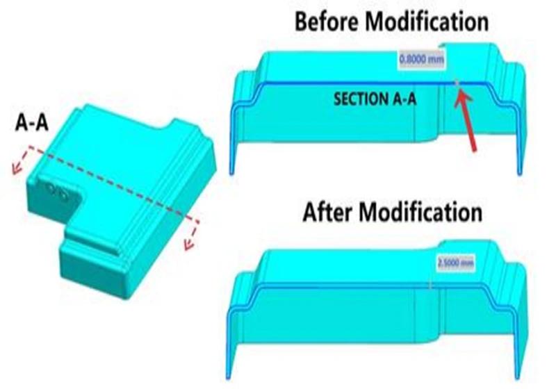
Comparison of Cross-Sections Before and After Wall Thickness Optimization
2)Draft and Draft Angle
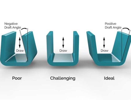
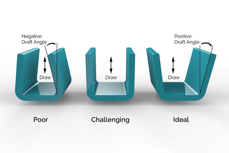
Insufficient or missing draft angle is one of the most common causes of production failures in small- and medium-volume injection molding.
General industry recommendations are:
- Smooth surfaces: minimum draft angle of 0.5°–1°
- Textured surfaces (VDI / EDM Texture): ≥2°
- Deep cavities and long core structures: ≥1.5°
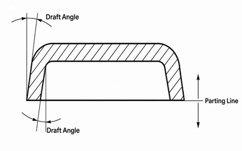
Draft Angle Structure Illustration
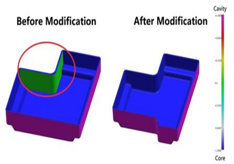
Comparison Between 0° Draft and Optimized Draft Design
3)Rib and Boss Design
Ribs and screw bosses are the primary structural features used to improve stiffness and provide assembly locations. They are also the areas where sink marks occur most frequently.
Typical DFM design guidelines include:
- Rib thickness = 50%–60% of the nominal wall thickness
- Rib thickness should generally not exceed 70% of the nominal wall thickness
- Screw boss roots should include an R0.3–R0.5 fillet radius together with proper core-outdesign to reduce material accumulation.
If the rib thickness is greater than about 60% of the nominal wall thickness, too much material will collect at the base of the ribs. The thicker area cools and shrinks differently from the rest of the wall and will almost always exhibit sink marks. However, if the ribs are too thin, they can fill in too low or short or there may be inadequate structural integrity. A proper rib thickness can greatly reduce any sink marks and provide adequate rigidity and strength.
4)Corner Radius
One of the most frequent problems in injection molded parts design is that of sharp internal corners. They tend to cause stress concentration, increase melt flow difficulties and initiates cracking.
Common DFM suggestions are:
- Use radius transitions wherever possible.
- Exterior cosmetic corners: R ≥0.5
- Structural load-bearing corners: R ≥0.8
- Avoid sharp 90° corners whenever possible.
5)Undercuts and Side Features
Slots, side holes, undercuts and other side features must be demoulded by the use of sliders, lifters or side-core mechanisms. These features are one of the main factors in the cost and maintenance of molds.
DFM optimization generally follows the following priority:
- Eliminate the undercut through product redesign.
- Use forced demolding whenever feasible.
- Add mold mechanisms only when necessary.
Typical engineering guidelines include:
- Undercut depth <0.5 mm: In general, forced demolding is preferred.
- Under cut depth 0.5-1.2 mm: Optimize the draft angle and chamfer geometry to minimize the demoling force.
- Undercut depth>1.2mm: Product redesign is normally proposed to prevent complicated non-standard mold mechanism.
6)Gate, Runner, and Venting System
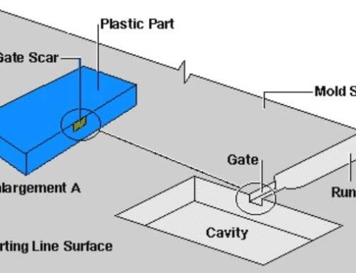
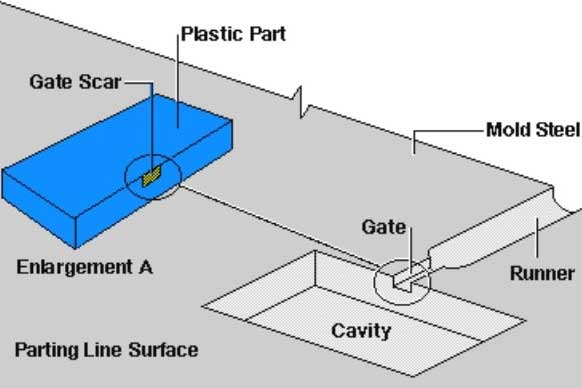
Gate location directly affects melt flow pattern, weld line location, residual stress, and final part quality.
General DFM recommendations include:
- Locate gates away from cosmetic surfaces, load-bearing areas, and assembly features.
- Use balanced runner systems to ensure consistent filling among multiple cavities.
- Fan gates and edge gates are generally preferred over pin gates to improve material utilization and reduce flow marks and jetting.
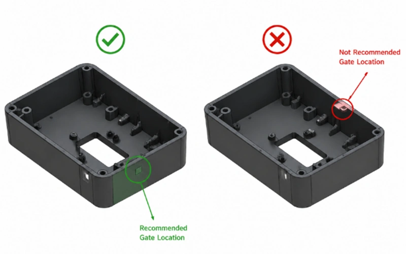
Gate Location Comparison
Proper venting is equally important.
Vent grooves should be provided at the end of melt flow and around weld line locations.
For most thermoplastics, a typical vent depth is 0.02–0.05 mm.
Proper venting helps reduce:
- Short shots
- Burn marks
- Weak weld lines
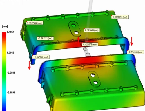
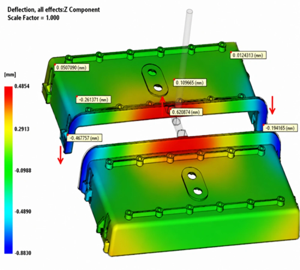
While this is on-going, CAE Moldflow Analysis can simulate the filling trend, pressure distribution, cooling imbalance before mold manufacture to optimize the gate location and move the weld line to other locations.
5. Typical DFM Findings and Engineering Solutions
Usually the function of the product will not be altered with DFM changes in most projects. They do so, however, by optimizing the structure in a localized fashion to improve manufacturability.
The table below provides a summary of the most-frequently discovered findings on a DFM Review and the engineering solutions.
| DFM Finding | Root Cause | Manufacturing Risk | Engineering Recommendation |
| Excessive local wall thickness variation | Uneven material volume causes inconsistent cooling and shrinkage | Sink marks, internal voids, warpage, dimensional variation | Core out thick sections to reduce material accumulation, maintain uniform wall thickness, and provide smooth wall thickness transitions |
| Insufficient draft angle on cosmetic surfaces or deep side walls | Draft angle was not designed according to texture depth or demolding resistance | Scratches, whitening, surface damage, difficult ejection, deformation | Select draft angles according to surface finish requirements. Smooth surfaces generally require a minimum of 0.5°, while textured surfaces require larger draft angles depending on texture depth. |
| Rib thickness exceeds 60% of nominal wall thickness | Excessive material accumulates at rib roots, causing differential shrinkage | Visible sink marks directly above rib locations, resulting in poor cosmetic quality | Reduce rib thickness to 50–60% of the nominal wall thickness while maintaining structural rigidity |
| Screw boss root is excessively thick or solid | No core-out design results in excessive material accumulation | Severe sink marks, internal voids, cracking, or stripped threads during screw assembly | Core out the boss root and add supporting ribs where necessary to balance strength and material distribution |
| Excessive flow length with a single gate | Single gate layout results in excessive pressure loss and insufficient packing | Short shots, incomplete filling, unstable dimensions | Add auxiliary gates or relocate the gate to reduce maximum flow length and improve filling balance |
| Large unsupported thin-wall areas | Insufficient structural rigidity leads to uneven stress release during cooling | Overall warpage, poor flatness, inconsistent assembly gaps | Add uniformly distributed reinforcing ribs on non-cosmetic surfaces to improve stiffness and balance internal stress |
| Gate located on a primary cosmetic surface | Gate location was selected without considering cosmetic appearance | Visible weld lines, flow marks, gas marks, and gate vestiges | Relocate the gate to a hidden or non-cosmetic area and optimize melt flow balance |
| Uneven cooling channel layout | Cooling channels do not adequately cover thick sections | Differential cooling causes uneven shrinkage and persistent warpage | Optimize cooling channel spacing and layout. Add additional cooling channels or baffles around thick sections to improve cooling uniformity. |
In our practice, experienced DFM engineers rarely optimize a single feature in isolation. Every recommendation is a balance between part performance, tooling complexity, manufacturing cost, production stability, and project priorities.
6. What Does a Professional DFM Report Look Like?
What should a professional DFM Report include? While report formats vary from company to company, a comprehensive DFM Report typically contains the following sections.
| Section | Purpose |
| Executive Summary | Overall manufacturing risk assessment and modification priorities |
| Part Geometry Review | Evaluation of wall thickness, ribs, bosses, corners, and other structural features |
| Draft Analysis | Draft direction analysis and draft-related risk assessment |
| Parting Line Review | Recommended parting line location and its impact on appearance and tooling |
| Gate Recommendation | Recommended gate location, quantity, and gate type |
| Moldability Assessment | Manufacturing risk assessment covering filling, demolding, cooling, and related processes |
| Engineering Summary | Engineering recommendations and next-step development suggestions |
The first page of a DFM Report usually provides an overall assessment of the product,
for example:
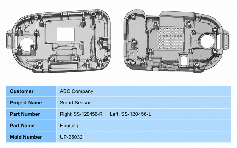
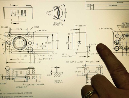
The following sections then identify each issue in detail and annotate the corresponding locations directly on the CAD model with specific engineering recommendations, rather than simply indicating whether the design “passes” or “fails.”
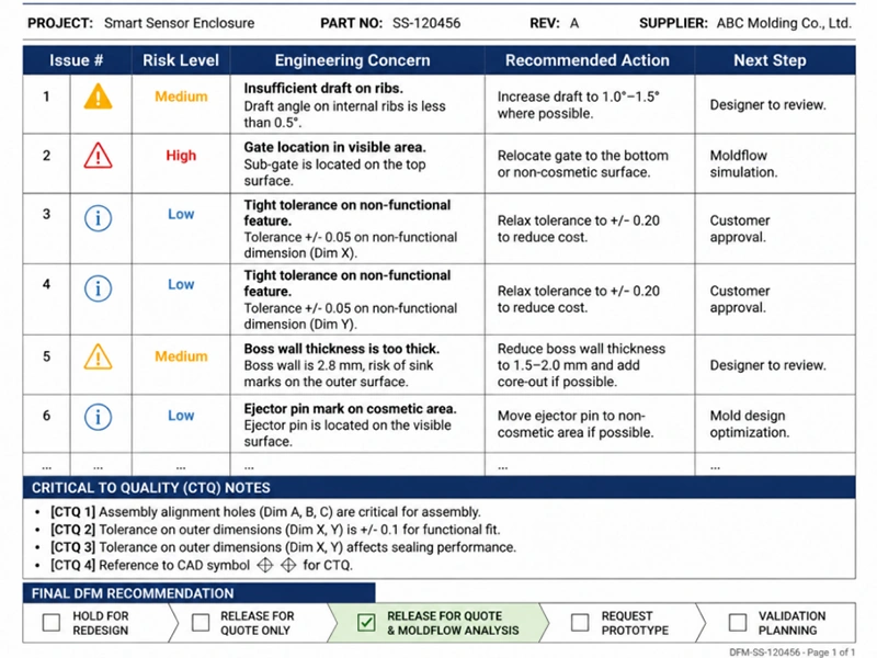
The real value of a DFM Report is not the colored screenshots, but providing clear engineering decisions on:
- Which issues must be modified;
- Which issues are recommended optimizations;
- Which manufacturing risks are acceptable;
- Whether the project is ready to proceed to Tool Design.
7. Case Study: Full-Process Improvement Analysis of an Automotive Interior Trim Panel
Using an automotive interior trim panel as an example, this case study combines actual defect photos, Moldflow simulation results, and optimized production parts to demonstrate the original design issues identified during the DFM Review, the corresponding engineering solutions, and the resulting improvements in mass production performance.
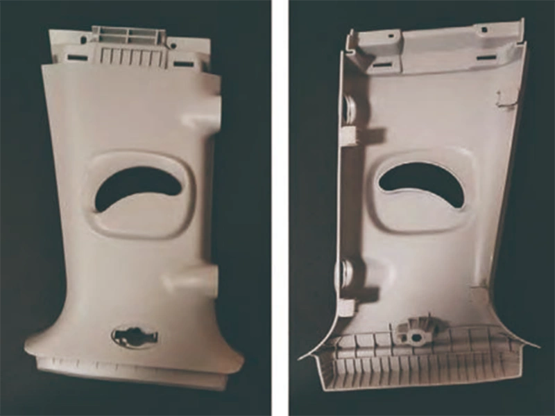
Original Defective Part vs. Optimized Production Part
1)Project Information
This project involved an automotive ABS interior trim panel with a high-gloss cosmetic surface. The part measured 210 × 145 × 32 mm and had an annual production requirement of 100,000 pieces.
The original design entered mold manufacturing without a dedicated DFM Review. Even after three mold trials, the part still failed to meet quality requirements due to four major issues:
- Sink marks
- Warpage
- Demolding scratches
- Cosmetic defects
The initial production defect rate reached 9.2%.
2)Major Issues Identified in the Original Design
a) Inconsistent Wall Thickness Design
The nominal wall thickness was 2.0 mm, while some reinforcing ribs reached 1.5 mm, equivalent to 75% of the nominal wall thickness.
Visible sink marks appeared directly above the rib locations.
In addition, localized wall thickness transitions reached 1.1 mm, resulting in uneven cooling and overall warpage of 0.8 mm.
b) Insufficient Draft Design
The side walls were designed with 0° draft.
During forced ejection, the high-gloss cosmetic surface exhibited severe scratches, ejector whitening, and drag marks.
The cosmetic defect rate exceeded 35%.
c) Redundant Structural Features
To help in assembly, a 0.6 mm undercut was designed along the product edge.
It was a good functional feature but it needed an extra lifter mechanism which added to the complexity of the mold, higher tooling cost and higher production risk during long production runs.
d) Unoptimized Gate and Venting Design
The original gate was located directly on the visible side surface, producing noticeable flow marks after molding.
Furthermore, no vent groove was provided at the end of melt flow, resulting in localized burn marks and raised weld lines.
3)Targeted DFM Improvements
a) Wall Thickness and Rib Optimization
The reinforcing rib thickness was reduced from 1.5 mm to 1.2 mm, meeting the recommended 60% wall thickness guideline.
An R0.4 fillet and a 0.3 mm core-out groove were added at each rib root.
The maximum wall thickness variation throughout the part was reduced to ≤0.6 mm, and thick sections were cored out to eliminate sink mark risk.
b) Draft Optimization
A standard draft angle of 0.75° was added to all cosmetic side walls.
Internal features were redesigned with 1° draft.
The high-gloss surfaces were polished to reduce demolding friction, allowing smooth ejection without forced demolding.
c) Undercut Simplification
The original 0.6 mm undercut was redesigned into a 0.4 mm shallow undercut.
Based on the flexibility of ABS, forced demolding replaced the lifter mechanism, significantly simplifying the mold structure.
d) Gate and Venting Optimization
The gate was relocated from the visible side surface to a hidden assembly area on the bottom of the part.
A fan gate was adopted to improve pressure distribution during filling.
A 0.03 mm precision vent groove was added at the end-of-fill region and previous weld line locations.
CAE Moldflow Analysis was used to optimize melt flow behavior, successfully eliminating flow marks and burn marks.
4)Production Results After Optimization
a) Quality Improvement
Sink marks, warpage, and demolding scratches were significantly reduced.
The overall production defect rate decreased from 9.2% to 0.8%.
b) Cost Reduction
The removal of the lifter mechanism reduced mold manufacturing cost by 28%.
Material utilization increased by 7%.
c) Production Efficiency
Cooling time was shortened by 2 seconds per molding cycle.
Overall production throughput increased by 12%.
8. Common Mistakes in Injection Molding DFM and Advanced Optimization Techniques
The following are Common Mistakes in Injection Molding DFM and Advanced Optimization Techniques.
1)Common Mistakes
The first common mistake is pursuing excessive lightweighting by blindly reducing wall thickness. This often causes the flow length ratio to exceed the recommended limit, resulting in short shots and incomplete filling.
The second mistake is ignoring the relationship between surface texture and draft angle. Applying the same draft angle used for polished surfaces to textured parts often leads to drag marks and surface damage during demolding.
The third error is the failure to pay attention to internal ribs and bosses uniformity. In spite of satisfactory appearance, it may have concealed defects, like sink marks and stress concentration. The fourth error is to over-reliance use process adjustment to overcome structural design flaws.
Optimizing the molding parameters to solve design problems is generally very difficult, which may lead to a very narrow molding window and poor production stability in the long run.
2)Advanced Manufacturability Optimization Techniques
Differentiated Draft Design
Different surface finishes require different draft angles. Typical engineering recommendations include:
- High-gloss surfaces: 0.5°–0.75°
- Fine textured surfaces: 2°
- Coarse textured surfaces: 3°
- Deep cavity structures: 1.5°
Selecting the appropriate draft angle according to the actual surface finish effectively prevents demolding defects.
Stress Relief Design
To prevent warping, engineers have traditionally used a symmetrical design that incorporates gradual wall thickness transitions for long, thin-wall parts that are prone to deformation and cooling shrinkage, and are likely to develop internal stresses.
Modular and Standardized Design
When the bosses, ribs, corner radii, and draft angles are standardized, non-standard machining of molds is reduced, the accuracy of mold manufacturing can be improved, and the mold modification and maintenance costs can be reduced.
9. Conclusion
DFM is used primarily to see if a product can be produced on a stable, economical basis prior to mold production. Moldflow Analysis, on the other hand, is used to further validate the molding behavior and production stability of complex parts. Whether your product is a thin wall, long flow, high cosmetic requirements, glass fiber reinforced, or requires tight assembly tolerances, a professional DFM Review should be conducted prior to tooling. You can send your 3D models to Holly Plastic Parts for a review and practical suggestions prior to mold making.