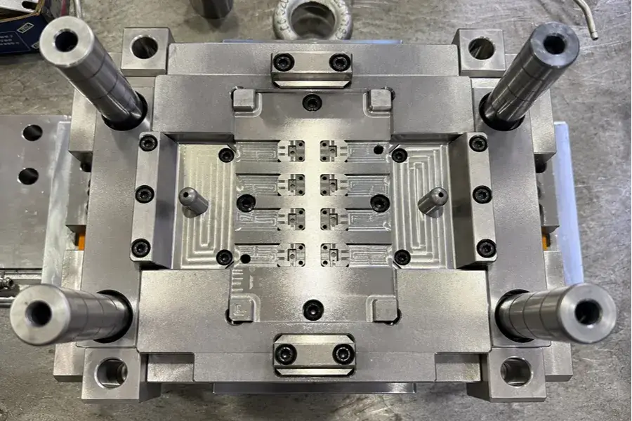
Injection molds are the core tooling for high-volume plastic part production. They directly determine product quality, production efficiency, and manufacturing cost. For the same plastic product, the mold design usually has a greater impact on successful mass production than subsequent injection molding process optimization.
This article introduces the fundamentals of injection molds, including their classification, major components, standardized manufacturing process, and common issues encountered during design, machining, and production maintenance. Based on practical engineering experience, it also analyzes the key control points in mold selection, manufacturing, and maintenance to help product development engineers, mold designers, sourcing teams, and manufacturing engineers establish a complete understanding of injection mold technology and support future mold development and mass production.
1. What Is an Injection Mold?
An injection mold is a production tool that uses an injection molding machine to inject molten plastic into a mold cavity. The plastic solidifies through packing, cooling, and ejection to form the final plastic part. Once the mold is completed, any design modification usually requires additional steel machining. Therefore, a well-designed mold has a much greater influence on project success than later process adjustments.
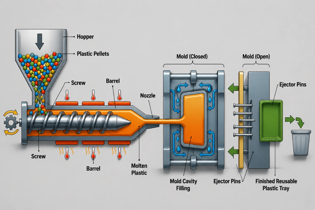
Injection Molding Process Diagram
2. Classification of Injection Molds
Injection molds can be classified from four perspectives: cavity count, runner system, mold structure, and molding process. Each category differs significantly in manufacturing cost, production efficiency, production volume, and product quality. These classifications are not mutually exclusive. A single mold can belong to multiple categories simultaneously. For example, one mold can be a 16-cavity hot runner three-plate mold while also being a two-shot injection mold.
1) Classification by Cavity Count
| Mold Type | Structural Features | Recommended Annual Production Volume | Relative Cost Factor | Advantages and Disadvantages |
| Single-Cavity Mold | One molding cavity per mold. The moving and fixed halves use a simple structure. | <100,000 parts, large parts, or high-precision cosmetic parts | 1.0 (Baseline) | Advantages: Easy cavity dimension control, no cavity balancing issues, and simple mold trials. Disadvantages: Low output per cycle and poor equipment utilization in high-volume production. |
| Multi-Cavity Mold (2/4/8/16 Cavities) | Multiple cavities are arranged in one mold with a balanced runner system. | 100,000–1,000,000 small standard parts | 0.6–0.8 per cavity (equivalent) | Advantages: Higher output per cycle and lower molding cost per part. Disadvantages: Runner balancing is more difficult, and dimensional or cosmetic variation between cavities is more likely. |
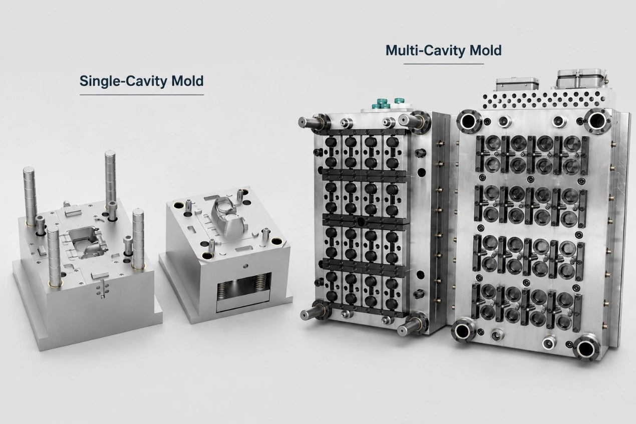
Single-Cavity Mold and Multi-Cavity Mold
2) Classification by Runner System
Cold Runner Mold: Molten plastic flows through the sprue, runner, and gate into the cavity. After molding, the runner solidifies and ejects together with the part, and the gate vestige must be removed manually or automatically. Cold runner molds feature a simple structure and low manufacturing cost. They are suitable for prototype production, annual volumes below 200,000 parts, and low-cost commodity plastics such as PP and standard ABS. Material utilization is typically 70%–82%.
Hot Runner Mold: Heating elements keep the runner system molten throughout the molding cycle, eliminating runner scrap and gate trimming. Material utilization generally exceeds 95%, while the molding cycle becomes shorter. However, mold cost increases by approximately 35%–80%. Hot runner molds are suitable for high-volume production exceeding 500,000 parts per year, including PET preforms, thin-wall electronic housings, precision thin-wall parts, transparent optical components, and high-value engineering plastics such as PC, PA66, and PEEK.
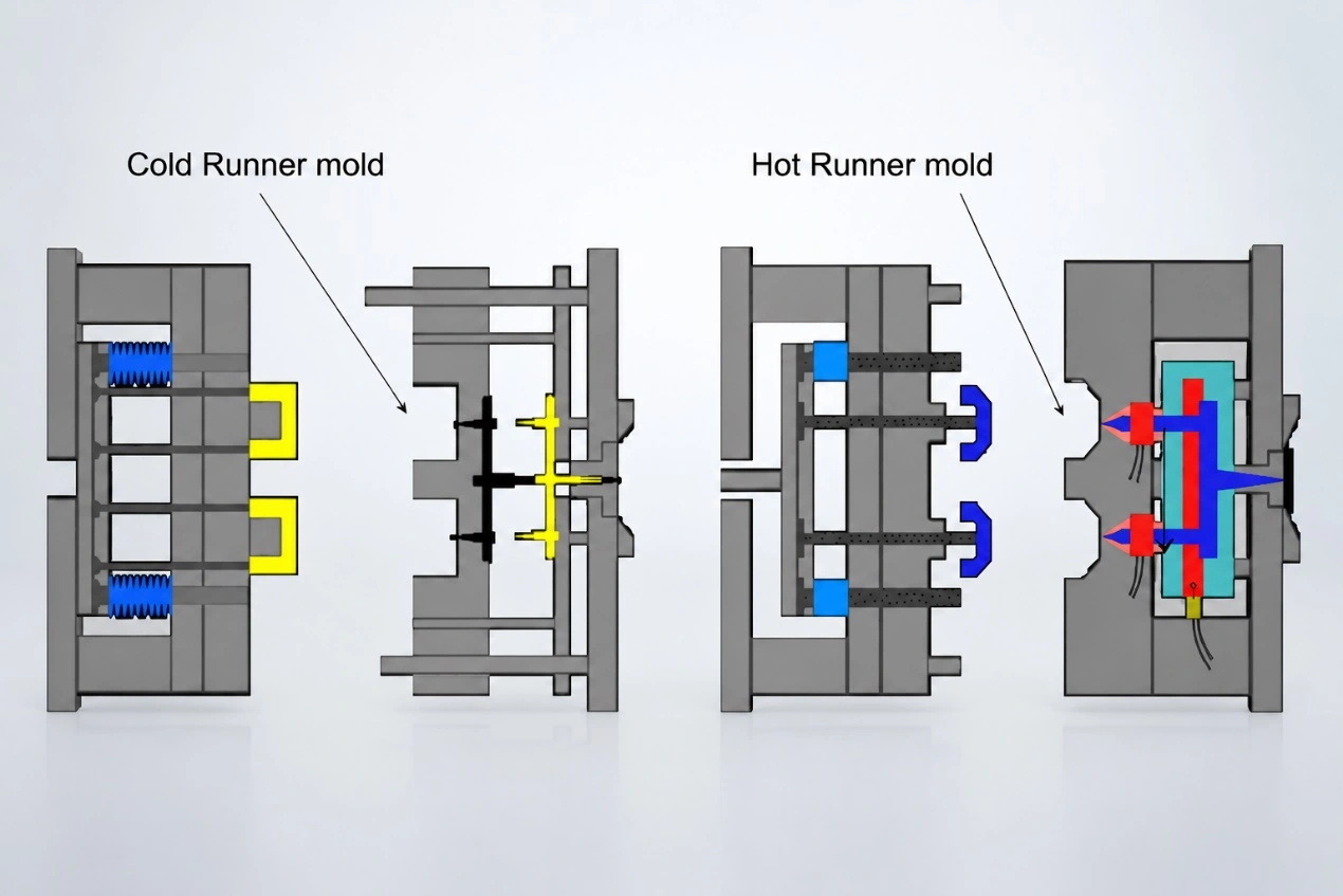
Cold Runner and Hot Runner
3) Classification by Mold Structure
Two-Plate Mold: The basic parting structure consists of only the moving half and the fixed half. Gates are located directly on the parting line, such as edge gates and fan gates. This design offers a simple structure, low manufacturing cost, and easy assembly and maintenance. However, gate marks remain on the side of the product, and the runner must be trimmed after molding.
Typical Applications: General consumer products, home appliances, industrial components, simple housings, and conventional gate types such as edge gates and submarine gates.
Three-Plate Mold: A runner plate is added between the moving and fixed halves, creating a three-plate structure consisting of the fixed clamping plate, runner plate, and moving plate. It is typically used with pin gates, allowing the runner and molded part to separate automatically during mold opening. The gate vestige on the product is very small and requires no manual trimming. However, the mold is thicker and more complex, resulting in higher manufacturing cost and a slightly longer molding cycle than a two-plate mold.
Typical Applications: Consumer electronics and appliance housings that do not allow visible gate marks, as well as round parts, thin-wall parts, large flat components, and products requiring multiple gate locations.
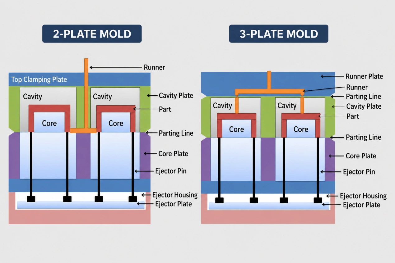
Two-Plate Mold and Three-Plate Mold
4) Classification by Special Molding Process
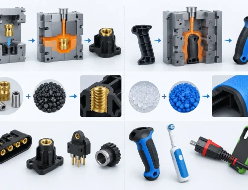
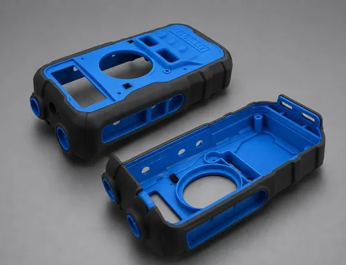
Two-Shot / Multi-Shot Injection Mold: Uses two independent cavities and a rotating core structure to mold two different colors or two different material hardness levels in a single molding cycle, such as toothbrush handles and soft-touch automotive interior components.

Multi-Shot Injection Molded Product
Gas-Assisted Injection Mold: Incorporates a nitrogen injection system to introduce high-pressure nitrogen into thick-wall sections, reducing sink marks and product weight. It is commonly used for thick handles and appliance housings.
Stack Mold: Arranges two cavity layers vertically, effectively doubling production capacity under the same clamping force. This design is mainly suitable for small standard thin-wall parts.
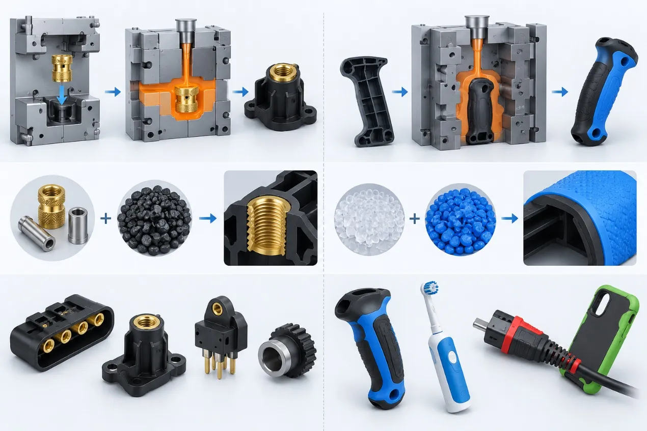
Insert Injection Mold: Integrates pre-positioned metal inserts such as terminals or brass threaded inserts into the mold, allowing metal and plastic to be molded into a single component. It is widely used for connectors and sensor housings.
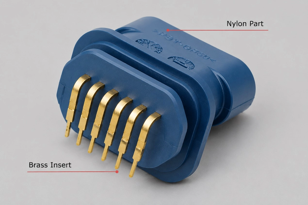
Insert Molded Product
3. Main Components of an Injection Mold
A complete injection mold consists of six independent systems: the mold base system, core and cavity, runner system, cooling system, ejection system, and venting system. These systems work together to complete melt filling, cooling, ejection, and gas evacuation. Any design weakness in one system can affect product quality and production efficiency.
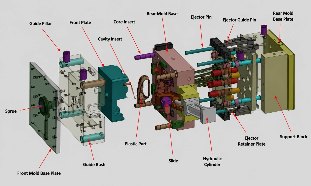
Injection Mold Structure
1)Mold Base System
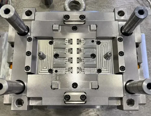
The mold base consists of guide pillars, guide bushes, locating pins, and stop blocks. It supports and houses all functional components while maintaining alignment accuracy and overall rigidity during mold opening and closing.
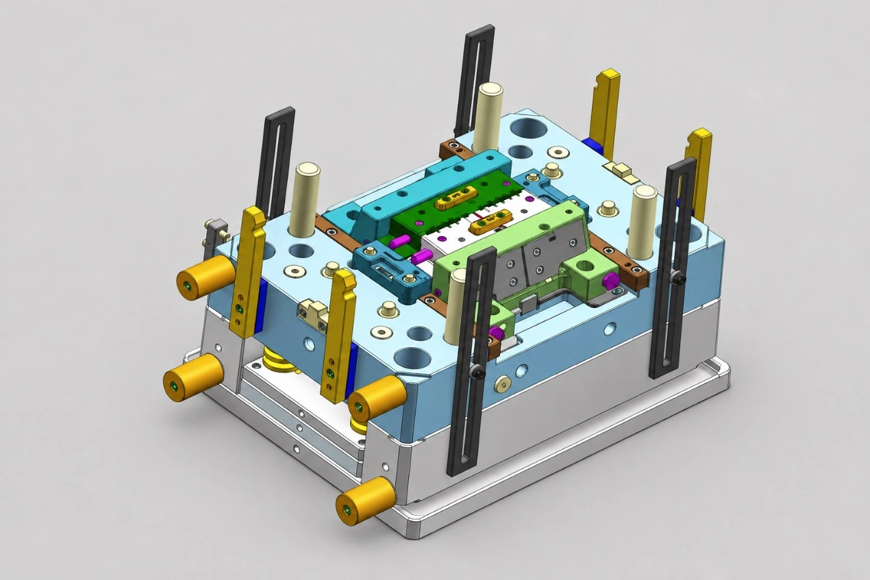
Mold Base System
General Requirements: Medium and large molds should use at least four guide pillars arranged symmetrically at the four corners. Guide pillars and guide bushes should have a heat-treated hardness above HRC 50. Install support pillars beneath the moving platen with spacing not exceeding 300 mm to resist platen deflection caused by clamping pressure.
Design Considerations: Confirm that the mold base meets the product size and clamping-force requirements. Reserve sufficient installation space for sliders, hydraulic cylinders, hot runner components, and other mechanisms. The layout should also allow easy maintenance, part replacement, and routine servicing. Export molds and long-term mass-production molds normally use standardized mold bases to shorten the manufacturing lead time and reduce future maintenance costs.
2)Core and Cavity
The core, also called the male mold, and the cavity, also called the female mold, are the primary molding components. They directly define the internal and external geometry, dimensional accuracy, and surface finish of the molded part. They are also the main focus of mold steel selection and heat-treatment control. The following table compares commonly used materials and parameters:
| Steel Grade | Heat-Treated Hardness (HRC) | Recommended Annual Production Volume | Corrosion Resistance | Maximum Polish Level | Relative Material Cost |
| P20 Prehardened Steel | 28–32 | ≤500,000 parts | Poor | Matte or textured finish | 1.0 (Baseline) |
| 718H Prehardened Steel | 33–38 | 500,000–800,000 parts | Average | Fine matte or high-gloss finish | 1.3 |
| NAK80 Prehardened Steel | 38–42 | 300,000–1,000,000 parts | Moderate | Mirror finish, up to #15000 | 1.8 |
| S136 Hardened Stainless Steel | 48–52 | >1,000,000 parts or corrosive plastics such as PVC and flame-retardant ABS | Excellent | Ultra-mirror optical finish | 3.0 |
| H13 Hot-Work Tool Steel | 48–52 | Abrasive glass-fiber-reinforced plastics such as PA66+GF and PPS | Average | Standard polish | 2.5 |
Note: Relative material cost uses P20 = 1.0 as the baseline and only compares the cost of different steels. Actual prices vary by brand, specification, and heat-treatment process.
Design Considerations: Verify that shrinkage compensation is reasonable. Use insert structures where appropriate to simplify repair and local replacement. Ensure that details such as radii, draft angles, and reinforcing ribs support machining and demolding. Select mold steel and surface treatment according to the molding material and production conditions.
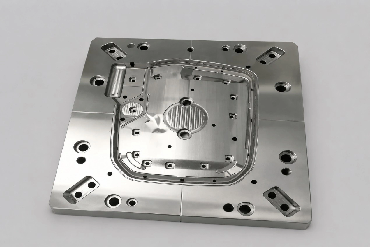
Cavity
3)Runner System
The runner system carries molten plastic from the injection molding machine nozzle to the cavity. It includes the sprue, runners, cold slug well, and gate. Gate design directly affects product appearance, weld-line location, and molding pressure.
Design Considerations: Position the gate to support balanced filling. Use suitable runner lengths and cross-sections to reduce pressure loss. Multi-cavity molds must maintain flow balance. The design team should also determine whether a hot runner or cold runner system is more suitable. Gate location should normally be verified through Moldflow analysis instead of relying only on past experience.
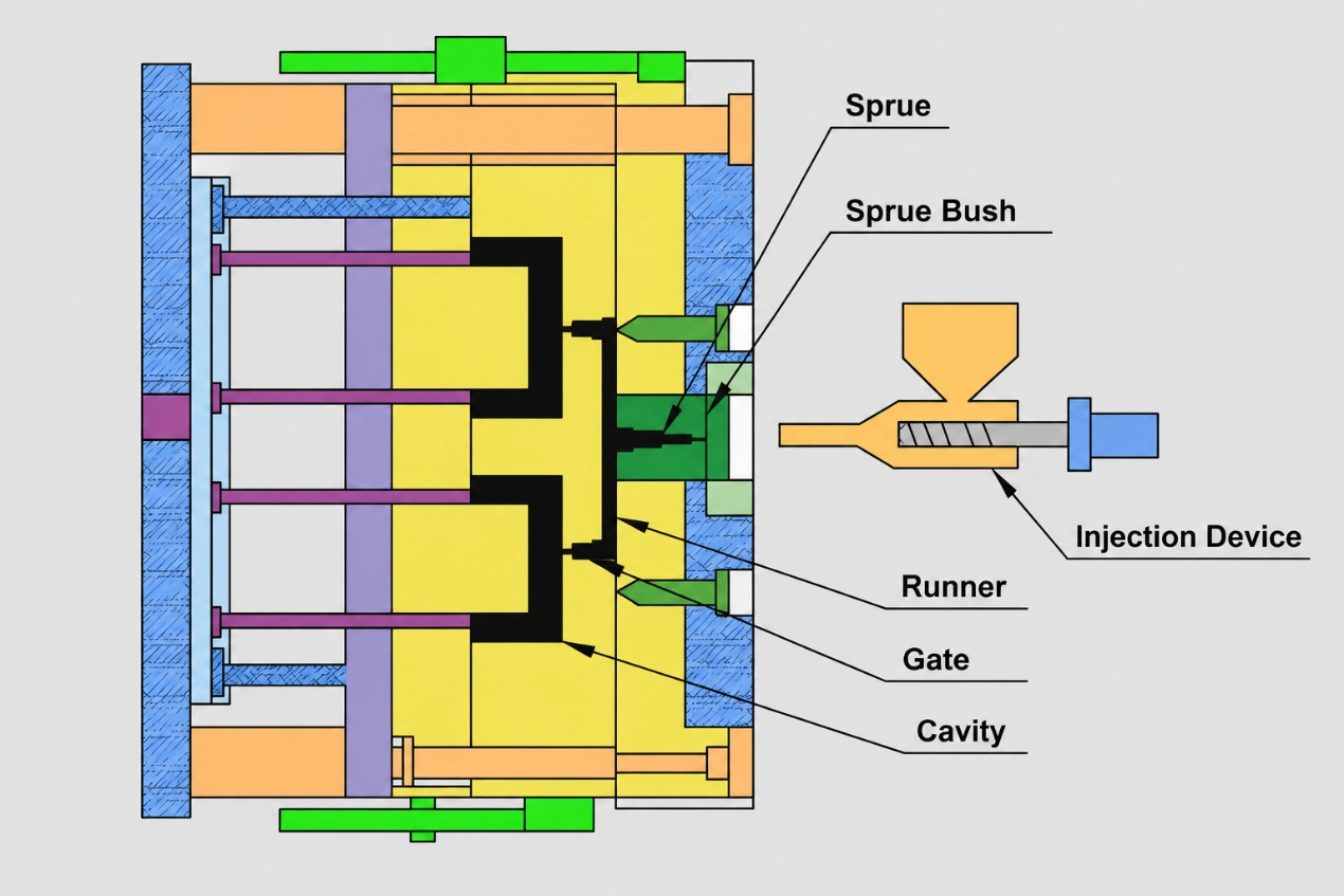
Runner System
4)Cooling System
The cooling system consists of circulating water channels, water fittings, sealing O-rings, and interfaces for the mold temperature controller. Temperature-controlled cooling water removes heat from the mold. The system directly determines molding-cycle time, shrinkage uniformity, and the degree of part warpage.
Design Considerations: Ensure that the cooling channels cover the product evenly. Avoid local hot spots and cooling dead zones. Maintain a suitable distance between the channels and the cavity surface. Use special solutions such as conformal cooling when conventional channels cannot provide uniform heat removal.
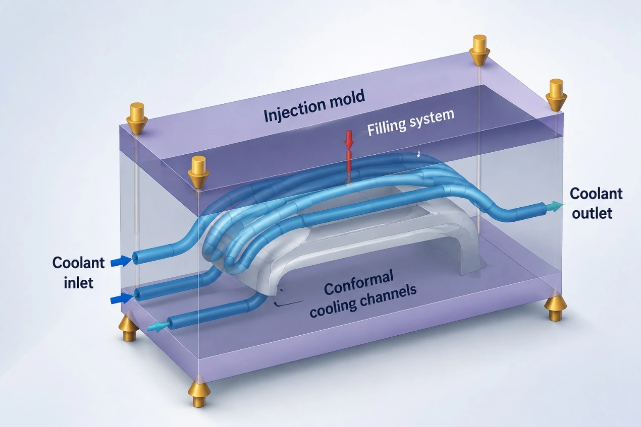
Cooling System
5)Ejection System
The ejection system removes the part from the mold after cooling. Common methods include ejector pins, stripper plates, ejector sleeves, and air ejection. Poor ejection design can cause stress whitening, cracking, deformation, or part sticking.
Design Considerations: Distribute the ejection force evenly. Keep ejector pins away from cosmetic surfaces where possible. Avoid excessive local loading and confirm that the part can release smoothly. For thin-wall or high-gloss parts, design the ejection system together with the demolding direction and product geometry.
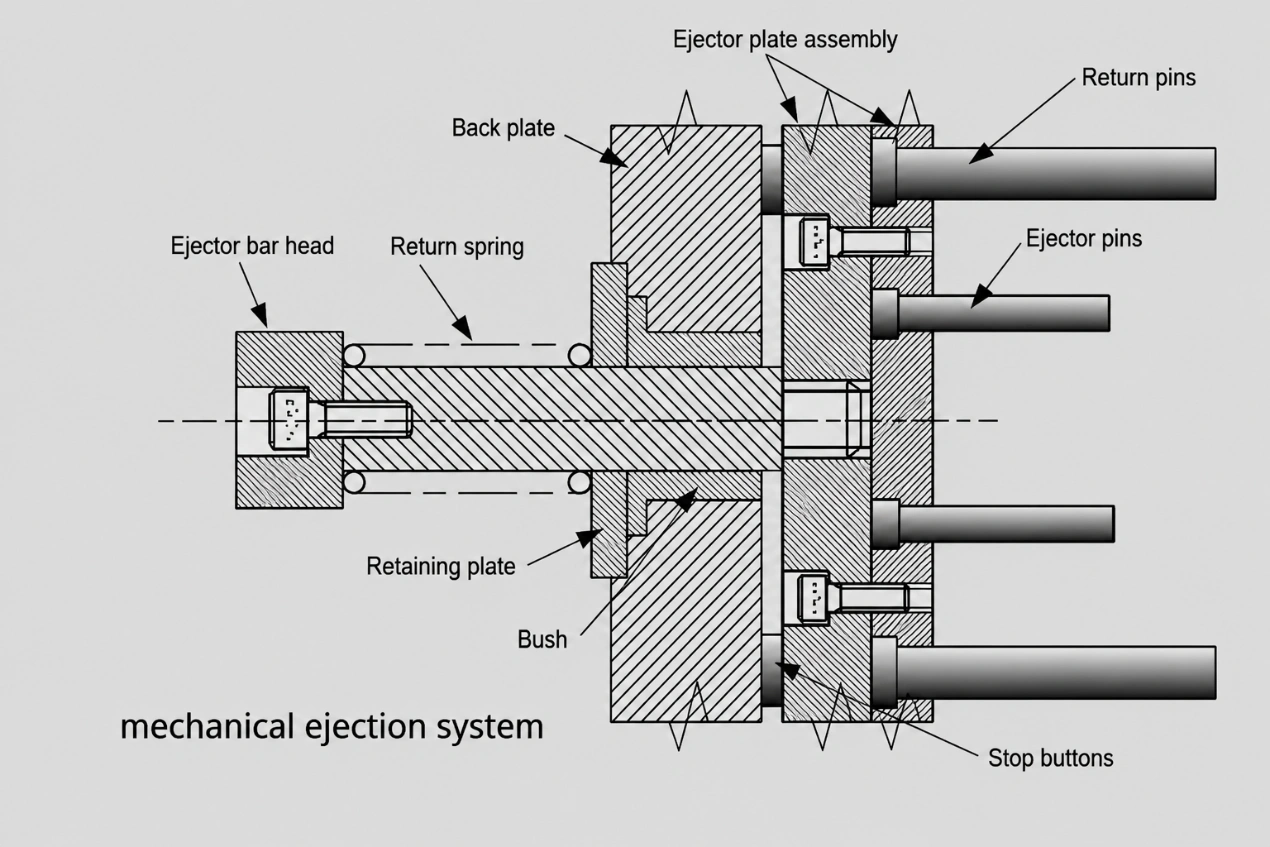
Ejection System
6)Venting System
The venting system releases trapped air and volatile gases from the cavity. Insufficient venting can cause short shots, burn marks, gas streaks, or reduced weld-line strength. These issues become more severe in high-speed molding and thin-wall applications.
Design Considerations: Place vent grooves at the final filling areas. Match vent depth to the molding material. Use the parting line, ejector pins, or inserts to provide auxiliary venting where necessary. Design the grooves for easy cleaning and maintenance after extended production.
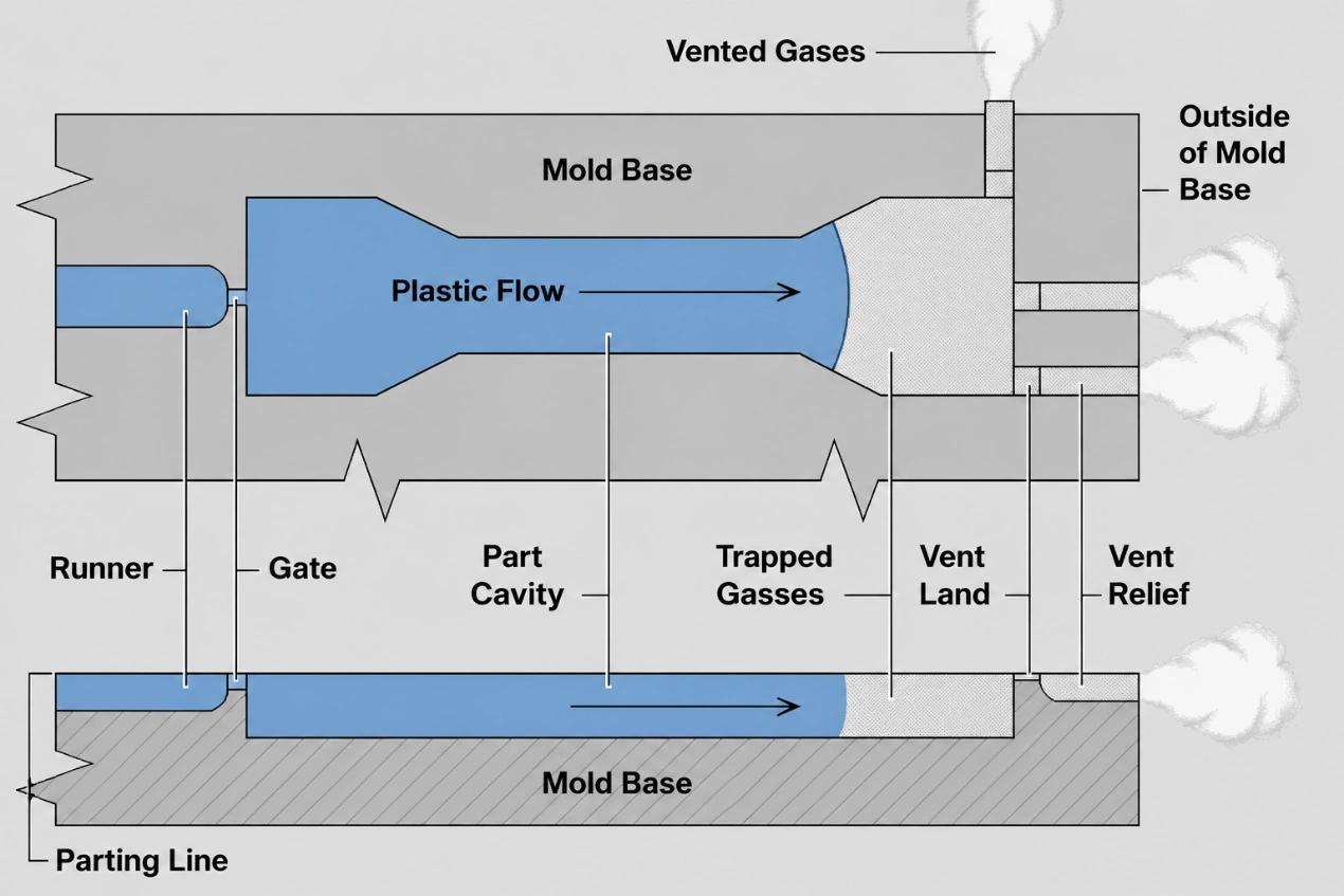
Venting System
4. Standardized Injection Mold Manufacturing Process
A complete mold development and manufacturing project includes six closed-loop control stages. The standard sequence is “design review—detailed structural design—raw material procurement—machining and processing—trial and adjustment—final documentation.”
Stage 1: Product DFM Review
Core Work: Analyze the injection-molding feasibility of the product 3D model and issue a DFM review report. The team should identify design risks early and reduce later mold modifications. Mandatory review items include wall-thickness uniformity, with thickness variation controlled within 20%; draft angle, with at least 1.5° on cosmetic surfaces and 0.5° on non-cosmetic surfaces; undercut structures; corner transitions; available space for gate layout; available space for cooling channels; and interference risks in the ejection system.
Work When Required: For thin-wall parts, warpage-sensitive parts, and multi-cavity balanced parts, perform Moldflow CAE analysis in advance. Use the simulation to predict trapped air, weld lines, uneven cooling, shrinkage, and warpage risks, then optimize the product and mold structure before tooling begins.
Deliverables: DFM corrective-action list, Moldflow analysis report when required, and the approved product 3D model.
Stage 2: Detailed Mold Structure Design
Based on the approved product drawings, complete the full mold 2D engineering drawings and 3D assembly model. Fully design the five major systems, the slider and lifter side-core-pulling mechanisms, mold base, and standard components. After design completion, conduct an internal review to verify fit tolerances, cooling channels, ejection, venting, and steel specifications.
Deliverables: Mold 3D assembly model, complete component machining drawings, standard-parts list, and mold-steel procurement list.
Stage 3: Raw Material Procurement and Heat-Treatment Processing
Steel Procurement: Select the specified steel grades for molding components such as the cavity, core, and sliders according to the production volume confirmed during the DFM review. Use standard carbon steels such as 45# steel or S50C for non-molding structural parts, including the mold base, spacer blocks, and ejector plates, to control cost.
Rough Machining: Use CNC milling machines and surface grinders to rough-machine the steel, leaving a 0.3–0.5 mm allowance for finish machining.
Heat Treatment: Quench and temper the molding cavity, core, and sliders to achieve the hardness specified on the drawings. Correct heat-treatment distortion and regrind the surfaces to restore flatness.
Finish Machining: Use high-speed CNC machining, EDM, and WEDM to complete precision machining of the cavity, inserts, and sliders to the specified dimensional tolerances.
Stage 4: Surface Treatment, Polishing, and Mold Assembly
Surface Treatment: Apply texture etching, mirror polishing, or matte finishing according to the product appearance requirements. Control the polishing grade of cosmetic cavity surfaces and prevent visible polishing marks.
Component Preassembly: Preassemble and adjust guide pillars, guide bushes, ejector pins, ejector sleeves, cooling-water fittings, springs, and other standard components.
Final Assembly: Fully assemble the moving and fixed mold halves. After assembly, perform three inspections: use red lead compound to check parting-surface contact, conduct a 2 MPa cooling-circuit pressure-hold test to verify leakage prevention, and cycle the ejection system repeatedly to confirm smooth movement without binding.
Stage 5: Controlled Mold Trials by Level (T0/T1/T2/T3)
T0 Trial: Verify the basic mold functions. Check whether mold closing, ejection, cooling, and core-pulling mechanisms operate smoothly and whether the melt can completely fill the cavity.
T1 Trial: Inspect sample dimensions and appearance. Record sink marks, weld lines, warpage, flash, and dimensional deviations, then issue a mold-correction action list.
T2/T3 Trials: Conduct repeat trials after mold modification. Continue optimizing the process and mold structure until all dimensional, cosmetic, and reliability requirements are met.
For every mold trial, lock the injection process parameters and retain samples, dimensional inspection data, and cycle-time records to establish a complete mold-trial file.
Stage 6: Mold Acceptance, Documentation, and Transfer to Mass Production
Complete final acceptance after the mold runs continuously and stably for 72 hours without batch defects, mold binding, water leakage, or abnormal wear.
Deliver the complete documentation package, including the mold 3D model, 2D machining drawings, steel material certificates, heat-treatment reports, Moldflow analysis report, inspection data from each mold trial, standard spare-parts list, and standardized injection-molding process parameter sheet for mass production.
5. Common Issues in Injection Mold Development
Based on more than 10 years of on-site experience in mold shops and mass-production maintenance, the Holly team has summarized the most frequent failures across the full mold lifecycle, including design, machining, assembly, mold trials, and production. These issues fall into three categories: inherent design defects, machining and assembly defects, and production maintenance failures. The following sections also provide cause analysis and corrective actions for reference.
1)Inherent Defects During Mold Design
Issue 1: The runner system of a multi-cavity mold is not balanced, causing dimensional and cosmetic inconsistencies between cavities.
Failure Symptoms: During trials of an 8-cavity or 16-cavity mold, some cavities show short shots while others produce flash. Product weight and dimensional deviation exceed 0.1 mm, making batch dimensional control unacceptable.
Cause Analysis: Runner lengths and cross-sectional areas are inconsistent, creating significant differences in melt-flow resistance and cavity filling sequence. Gate sizes also do not match the corresponding cavity volumes.
Corrective Action: Use a fully balanced runner system for all multi-cavity molds. Keep the melt-flow length and runner cross-section identical for every cavity. Match the gate cross-sectional area to the volume of each individual cavity and slightly enlarge the gate for higher-volume cavities. During mold trials, measure the product weight from each cavity. Accept the mold when the weight variation is ≤3%. If the deviation exceeds this limit, modify the runner and gate again.
Issue 2: The cooling-channel design is unreasonable, causing excessive mold temperature variation, batch warpage, and dimensional drift.
Failure Symptoms: Individual samples meet dimensional requirements during the initial trial, but the parts gradually deform and continue to shrink after one hour of continuous production. Batch assembly gaps become unstable, and the shrinkage difference between the moving and fixed mold sides is visually apparent.
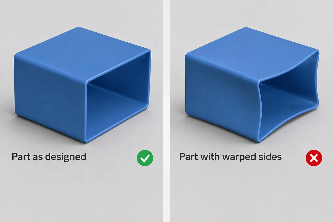
Part Warpage
Cause Analysis: Thick-wall and ribbed areas do not have conformal cooling channels. Cooling-channel spacing is too large, or the channels are too far from the cavity surface. The moving and fixed mold halves share one cooling circuit, preventing independent temperature control and creating a mold-wide temperature difference greater than 5°C.
Corrective Action: Arrange dedicated conformal cooling channels around thick-wall areas, dense ribs, snap-fit features, and bosses. Maintain a cooling-channel center distance of 30–50 mm and a distance of 15–25 mm from the cavity wall. Use two independent cooling circuits for the moving and fixed mold halves and control them separately with two mold temperature controllers. Keep the overall mold temperature variation within ±3°C. Avoid sharp bends and blockages in the channels. Use a high-flow circulation design with cooling-water velocity controlled at 0.8–1.2 m/s.
Issue 3: Defects in the ejection-system design cause stress whitening, punch-through, and demolding deformation.
Failure Symptoms: White stress marks appear around ribs and screw bosses. Ejector pins punch through thin-wall parts, and long, narrow housings bend after demolding.
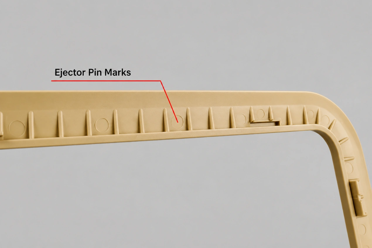
Ejection System Defects
Cause Analysis: Ejector pins are positioned improperly and concentrated in thin-wall areas. The design does not use ejector sleeves or blade ejectors for deep screw bosses and long ribs. The ejector plate has no support pillars, allowing the platen to deflect under clamping pressure and causing uneven ejection-force distribution.
Corrective Action: Distribute ejector pins evenly. Prioritize ejector sleeves for screw bosses and thick ribs to spread the ejection force. Add support pillars beneath the moving platen of flat-part molds, with spacing not exceeding 300 mm, to limit platen deflection. Apply an R-radius to the ejector-pin tips and polish the ejector holes to reduce friction and demolding stress.
2)Defects During Mold Machining and Assembly
Issue 1: Cavity machining deviation and poor polishing cause cosmetic defects and out-of-tolerance dimensions.
Failure Symptoms: Product surfaces show polishing lines, pitting, and EDM texture. Critical assembly holes and snap-fit dimensions shift across production batches, and CMM inspection shows out-of-tolerance results.
Cause Analysis: The finish-machining allowance is excessive, or EDM parameters are set incorrectly. Polishing steps for mirror-finish or high-gloss cavities are simplified, and the required polishing grade is not achieved. Dimensional tolerances are missing from the machining drawings, leaving operators without clear control criteria.
Corrective Action: After finish machining, leave no more than 0.03 mm of polishing allowance on molding cavities. Thoroughly grind the surface after EDM to remove electrical-discharge marks. Control polishing by grade: polish matte or textured parts to #800. Add CMM inspection for critical cavity dimensions. After machining, perform a complete dimensional inspection and allow the component to proceed to polishing and assembly only when dimensional tolerances are within ±0.02 mm.
Issue 2: Uncontrolled assembly clearances cause flash and slider seizure during mass production.
Failure Symptoms: Continuous thin flash appears along the parting line. Side sliders and lifters seize after repeated movement, preventing normal core pulling and causing frequent line stoppages for mold disassembly and repair.
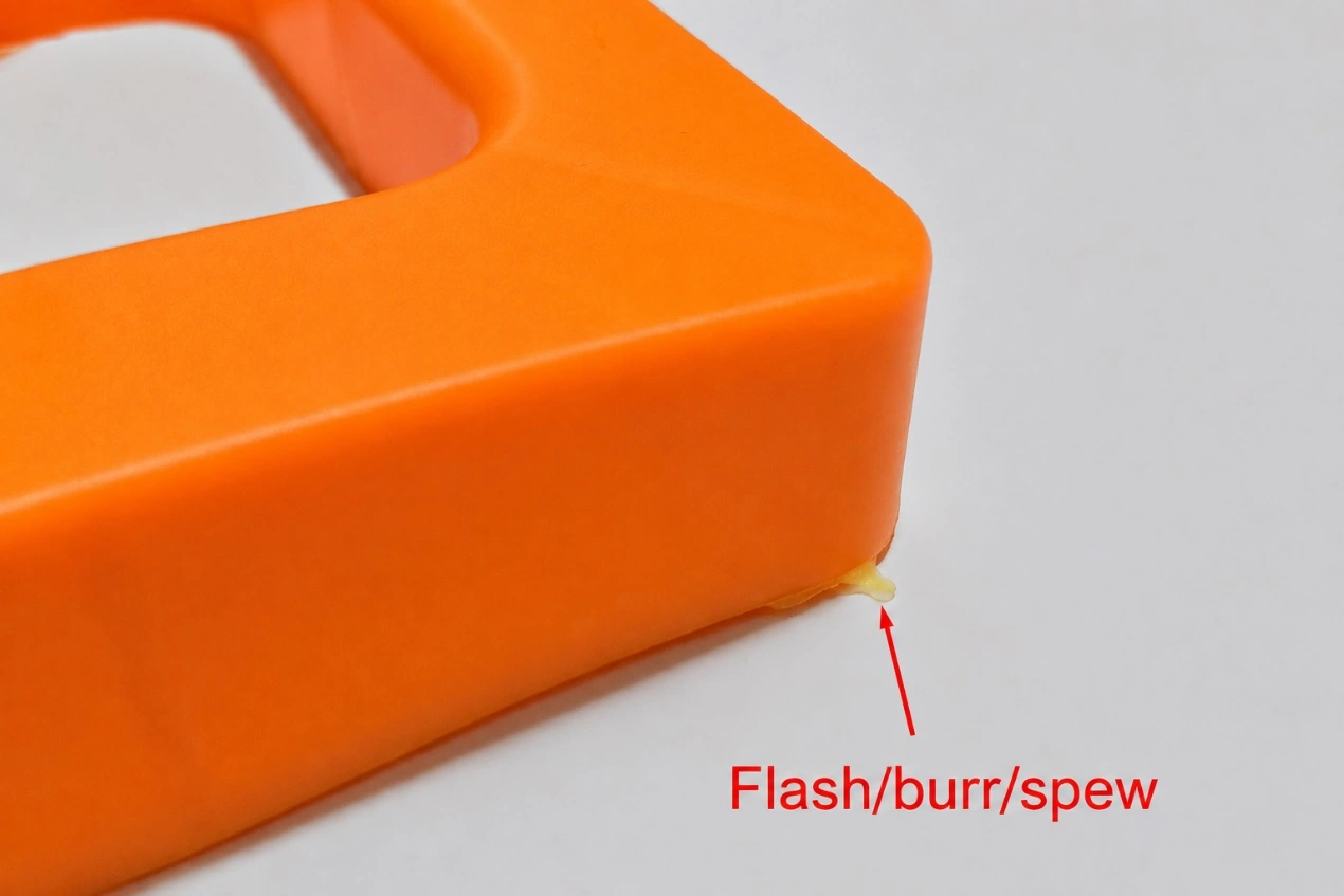
Flash Defect
Cause Analysis: Clearances between guide pillars and guide bushes, parting surfaces, and slider wear plates are excessive. Components deform after heat treatment, but the assembly process does not include fitting and spotting. Sliders have no wear plates or lubrication grooves, which accelerates wear during high-temperature mass production.
Corrective Action: Control standard fit clearances as follows: 0.01–0.03 mm between guide pillars and guide bushes, and 0.02–0.04 mm at slider wear surfaces. If the clearance exceeds the specification, grind and fit the components again. Install wear-resistant steel plates on sliders and lifters, and machine grooves to retain high-temperature grease. Apply the grease evenly before mass production. After assembly, use red lead compound to check parting-surface contact. The contact rate must be ≥95%. Grind out all local gaps.
3)Mold Failures During Mass-Production Operation and Maintenance
Issue: The molding cycle is continuously shortened, resulting in insufficient cooling time and ongoing post-molding shrinkage and deformation.
Failure Symptoms: To increase daily output, operators manually reduce the mold cooling time. The product is not fully solidified when it leaves the mold. After standing for 24 hours, the dimensions decrease and the housing warps, causing large-scale assembly failures.
Cause Analysis: The mold cooling system has limited heat-dissipation capacity. Forcing a shorter cooling cycle leaves the internal melt incompletely cooled and solidified, so the product continues to undergo time-dependent shrinkage after demolding. The production team also lacks standardized process control and changes parameters without authorization.
Corrective Action: Establish and lock the standard molding cycle. Cooling time must remain a mandatory process requirement and should be determined according to the material, wall thickness, and mold temperature. As an initial estimate, use the maximum wall thickness × 2–5 s/mm. No personnel may shorten the cooling time without approval. After molding precision parts, hold them at a constant temperature for 24 hours before dimensional inspection to eliminate errors caused by time-dependent shrinkage.
6. Summary
Injection molds provide the foundation for high-quality, low-cost mass production of plastic products. A high-performing mold requires not only a sound structural design, but also mature machining processes, strict assembly inspection, and standardized mold-trial verification. Only a complete quality-control system covering design, manufacturing, and mass production can maintain long-term production stability while reducing future maintenance and modification costs.
For injection mold development, product DFM analysis, or mold manufacturing requirements, please contact the Holly engineering team. We provide one-stop services covering product evaluation, mold design, mold manufacturing, mold-trial verification, and mass-production support. Our team helps shorten development lead times, reduce manufacturing costs, and achieve stable mass production.