Technical drawings (and the drawing process) are a way of transferring information between engineers and manufacturers. Technical drawings are usually supplements to digital CAD files, and the additional information provided cannot be conveyed simply by the shape of the part.
In the world of prototyping and manufacturing, we usually deal with certain subtypes of technical drawings called engineering drawings. These contain material and information collation requirements, partial information, and most importantly, partial 2D and 3D. View complete dimensions and tolerances from multiple angles.
This guide reviews the basics of technical drawings, discusses why they are needed, what elements are usually included, and how to prepare a technique.
1. Why do we need technical drawings
Technical drawings have existed for centuries, predating today’s digital manufacturing technology. Before the advent of computers, technical drawings were the main reference for manufacturers.
Today, people can design a part on a computer, and then send a digital file on the same computer to the machine that will manufacture the part, without the need for technical drawings. However, most important manufacturing jobs-even those that use digital manufacturing techniques-still require the use of technical drawings. why?
First, the technical drawing verifies the content contained in the CAD file, giving manufacturers confidence that what they are manufacturing is exactly what they need. The perfect association of CAD and drawings shows that there are no errors in the design. Once the part is completed, the drawing can be used as a reference for inspection.
Second, technical drawings can provide a lot of other information that is not in the CAD file. The information communicated through technical drawings may include:
- Tolerances for special characteristics
- Surface treatment requirements for specific surfaces
- Material requirements for specific components
- Internal or external threads
In a third case, technical drawings can serve as evidence in a court of law. Hence, they are part of the contract and of the purchase order: The customer can use the technical drawings if the manufacturer does not deliver the parts as specified as evidence of the unfinished design;
On the other hand, as long as it conforms to the technical drawings, the manufacturer is not liable. (If the CAD file is designated as a legal document on the drawing, it does not apply.)
In addition, manufacturers generally prefer to receive technical drawings with digital files because they can quickly evaluate the geometry, size, and potential cost of the part.
Finally, technical drawings are the only internationally recognized way to communicate engineering instructions; There is no ambiguity, no confusion, and nothing that could jeopardize the success of the project.
Introduction:
- Verify
- Information
- Legal documents
- Quick reference point
- Internationally recognized
2. Technical Drawing Standards
Technical drawings and engineering drawings are subject to several sets of generally recognized standards. These guidelines provide guidelines for drawing and help facilitate communication between different parties (including those who speak different languages).
The International Organization for Standardization (ISO) stipulates that technical drawings use ISO 128, and engineering drawings use ISO 8015. As part of its own drawing standards Y14.5 and Y14.5 m, the American Society of Mechanical Engineers (ASME) has also released its own standard.
It applies to technical drawings in the fields of mechanical engineering and contains general rules for the preparation of technical drawings (in 2D and 3D). construction, construction and shipbuilding”, including “manual and computer technical drawings.”
3. Technical drawing view and other features
A finished technical drawing contains several different views of the object, allowing the manufacturer to easily explain the engineer’s intentions. These views and other features are usually present in CNC machining drawings or sheet metal drawing layouts:
Isometric view: Isometric view or graphical view displays objects rotated 45 degrees around the vertical axis and 35.264 degrees around the horizontal axis. The purpose of this view is to provide a three-dimensional view of an object with the illusion of depth.
Orthographic view: Orthographic view is a two-dimensional description of an object, which can be seen from the front, right, left, top, bottom or back-called the main view. The combination of these orthographic views is called multi-view projection. In most cases, only two to three orthographic views are needed to convey the necessary information, and a drafter will usually include the minimum requirements.
Auxiliary view: Auxiliary view is any additional 2D view from the six main views.
Section view: The section view shows the cross-section of the object along the specified cutting plane. They are used to display the internal details of the part and are usually placed in the same position as the orthographic view.
Detailed view: The detailed view highlights the key or complex areas of the orthographic view.
Title block: The title block contains information such as part name, company name, part number, drawing number, material requirements, finishing requirements, colouring requirements, use ratios and use standards. It is usually placed in the lower right corner of the drawing.
Note list: May include notes for drawing users. These may be general notes or marked notes and can be placed anywhere on the edge of the drawing.
4. How to quickly prepare technical drawings
Thanks to modern CAD software, preparing technical drawings does not necessarily require the services of a professional cartographer. This section will discuss how to use CAD software to draw technical drawings, rather than how to draw on paper-this is a process that should be left to experts.
Slave model
The easiest way to prepare technical drawings is to automatically generate a drawing from the CAD design. For example, in SolidWorks, simply select “Draw from Part/Assembly” in the “Standard” toolbar, and then select a predefined template.
The software will automatically generate the selected views and features, and then the drawings can be exported. There are many benefits to drawing technical drawings from the model. For example, parts can be digitally “assembled” to ensure that they can be assembled together, and simulation tools can be run to ensure that the parts work properly.
Start from scratch
It is also possible to prepare technical drawings from scratch using CAD software. If you have no CAD experience and have not used CAD software to create parts, then this may be a better choice.
This is actually like drafting on paper, but using digital tools can reduce the chance of error. Please note that creating technical drawings from scratch does not allow digital assembly or simulation. Regardless of your preparation method, all technical drawings should include:
- Geometry/View
- Dimension
- Tolerance
- Material requirements
- Completion/color requirements
5. What should be included on the CNC machining technical drawings
When preparing technical drawings for CNC machining, some specific functions may need to be added. These include:
- Tolerance in a specific area: CNC machining is different from other manufacturing processes, and several machine tools can be used to process a single part. For example, machining can be roughed before face milling of detailed features. Therefore, different tolerances can be specified for different areas of the part and critical areas can be machined at a slower speed using better tools.
- Hole annotation: Hole is a common CNC machining feature, usually marked in the detailed view. Thread specifications: Since the threads are manufactured in standard sizes, it is helpful to specify the corresponding thread size for each thread, rather than the size in millimetres.
6. What should be included on the sheet metal technical drawing
When preparing technical drawings for sheet metal manufacturing, some specific functions may need to be added. These include:
- Material Table The material table-the thickness of the metal-has nothing to do with CNC machining and other processes, but it is very important for sheet metal forming.
- Grain direction: For stainless steel parts, for example, the direction of the grains may need to be clarified in the technical drawings, because the grains have an important influence on bending and other actions. Bending together with the die (longitudinal) requires less force, but will cause cracks in the external bending radius; Crooked grains (horizontal) require more force but protect the external curvature.
- Assembly torque requirements: Different materials and measuring tools can withstand different degrees of torque during the assembly process with screws.
- Welding position: The position (and size) of the welding point should be indicated in the drawing.
- The size of elbows, countersinks, and holes: the size of features such as countersinks should be specified.
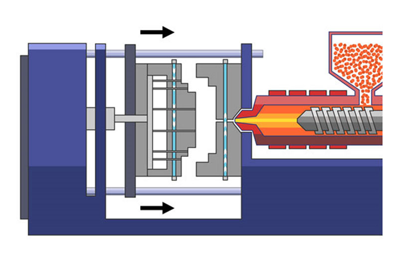
7. What should be included in the injection molding process drawings
It is possible to add some specific functions to technical drawings for injection molding. These include:
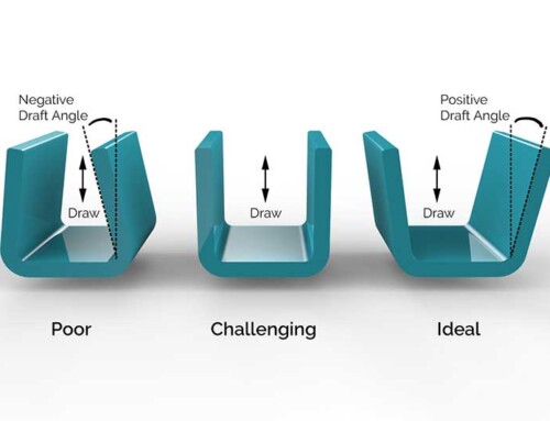
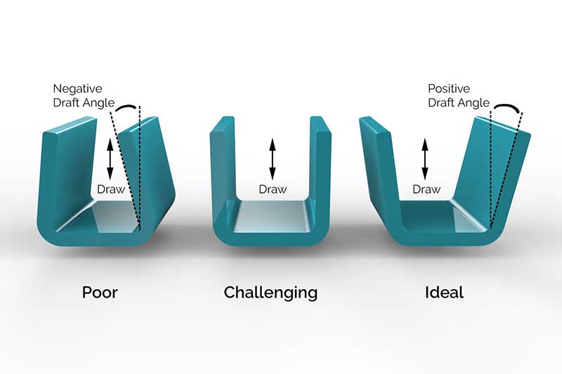
- Acceptable draft: In many cases, the injection molding company will determine the minimum draft angle required to facilitate injection from the mold. However, if the engineer believes that certain functions cannot accept high drafts (for example, because of the end-use of the product), this should be stated in the notes on the drawing.
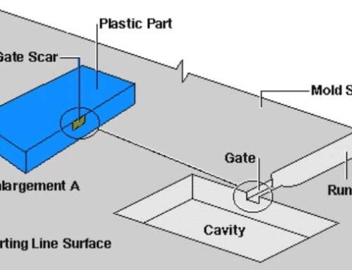
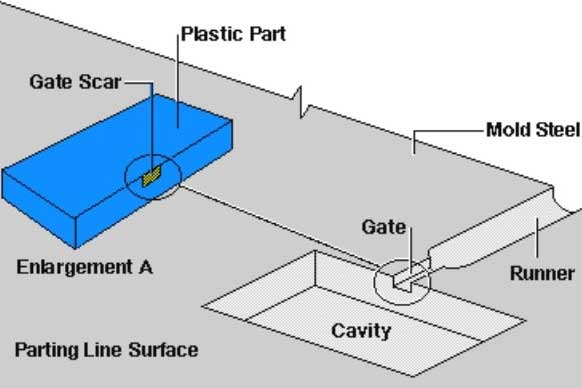
- Gate, ejector pin and parting line location restrictions: In most cases, the mold company will determine the location of the gate and pin.
However, in order to avoid unrealistic gate and pin locations, technical drawings can specify any unacceptable locations, and leave the final decision to the mold company.
8. What should be included in the die casting technical drawing
When preparing the die casting technical drawings, some specific functions may need to be added. These include:
- Acceptable draft: As with injection molding, casting technical drawings may specify any restrictions on draft angles.
- Gate and parting line location restrictions: Like injection molding, technical drawings can specify any unacceptable gate or parting line location, leaving the final decision to the casting company.
- Wall thickness: In addition to the dimensions specified in technical drawings, wall thickness can be specified up to a certain thickness.
9. What should be included in the plastic/aluminium extrusion technical drawing?
When preparing extrusion technical drawings, some specific characteristics may need to be added. These include:
- Blank size: The required metal blank size can be specified on the technical drawing.
- However, this is usually unnecessary.
- Grain direction: As with sheet metal parts, technical drawings can specify the grain direction of the metal to ensure that it is the strongest in a certain direction.
- Exposed surfaces: Extruded technical drawings may indicate that exposed surfaces require more attention to detail.
- Hole labeling: Holes are usually identified on detailed views of extrusion technical drawings.
Holly is a prototype and small batch manufacturing expert with many years of experience. If you are not sure whether you need to submit technical drawings, please communicate with us directly. If you have one ready, upload it or with your CAD file to get a quick free quote.