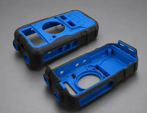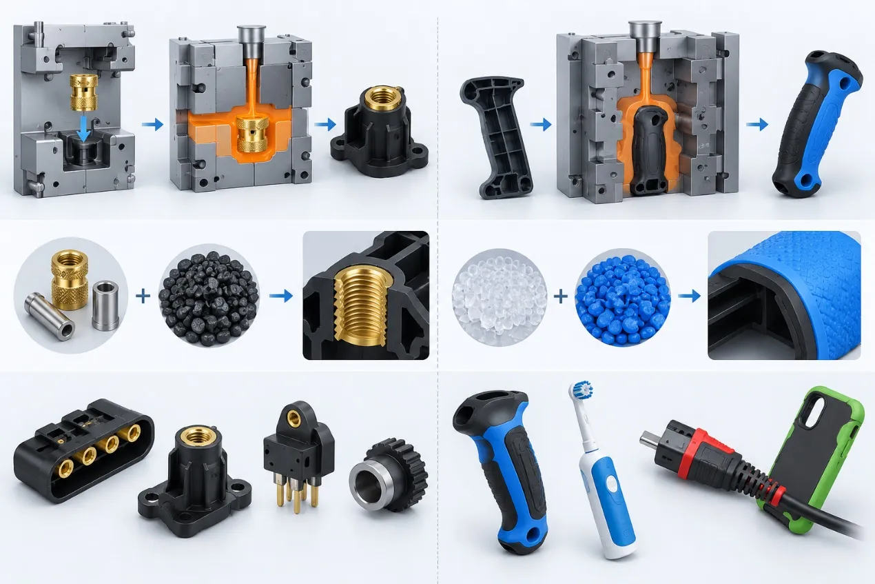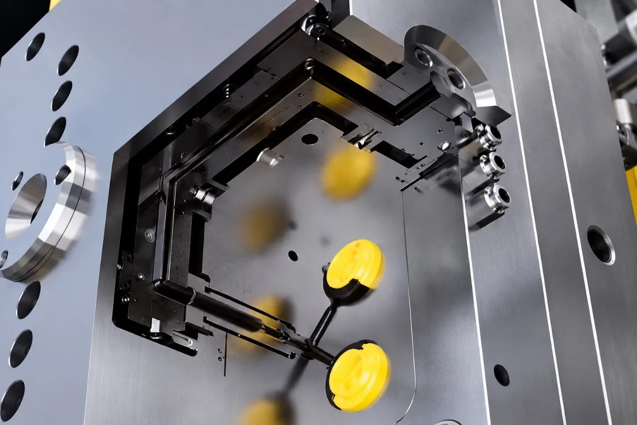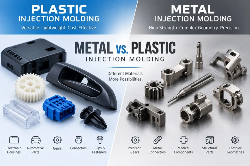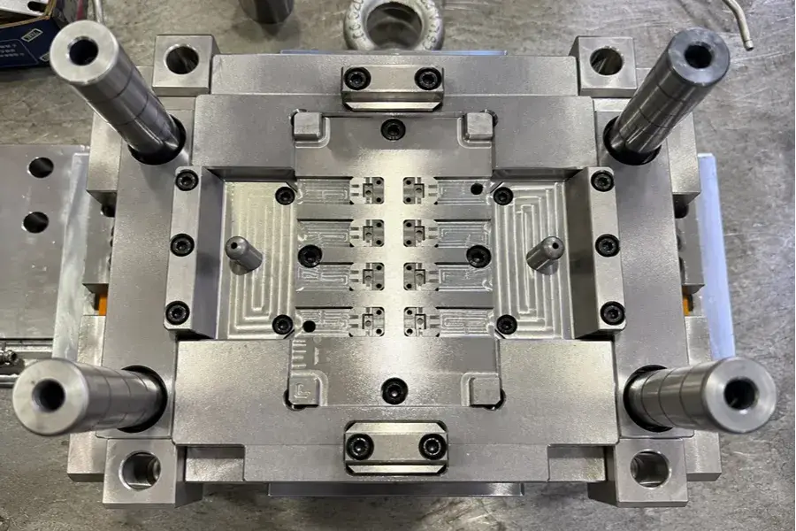
Thin-wall injection molding uses less material, less weight and less molding time to satisfy the lightweight requirements of Packaging, Consumer Electronics, Medical Products, and Automotive Parts. This guide introduces the concept and main design features of thin wall injection molding, the selection of materials, mold structure and control of injection parameters. It also looks at typical molding defects, the primary causes of such imperfections, and some of the most effective ways to improve them for engineering reference.
1. What Is Thin-Wall Injection Molding?
Thin-Wall Injection Molding is a type of injection molding which is employed to manufacture the thin-walled plastic parts. The thickness of a wall or the ratio of the length of flow to the thickness (L/T) of a part are generally used in engineering practice to determine whether the part is in this category:
- Wall Thickness: Parts below 1 mm are generally considered typical thin-wall parts. Parts with 1–2 mm walls can also show thin-wall molding characteristics when they have long flow lengths or large housing areas.
- L/T: This is the melt flow distance from the Gate to the Flow End ÷ wall thickness. An L/T below 150:1 is generally relatively easy to fill; 150:1–300:1 starts to require clear thin-wall filling capability; above 300:1 is considered a high L/T and normally requires a higher-flow material, a more suitable Gate layout, and stronger filling capability.
Note: The values above are engineering reference ranges.
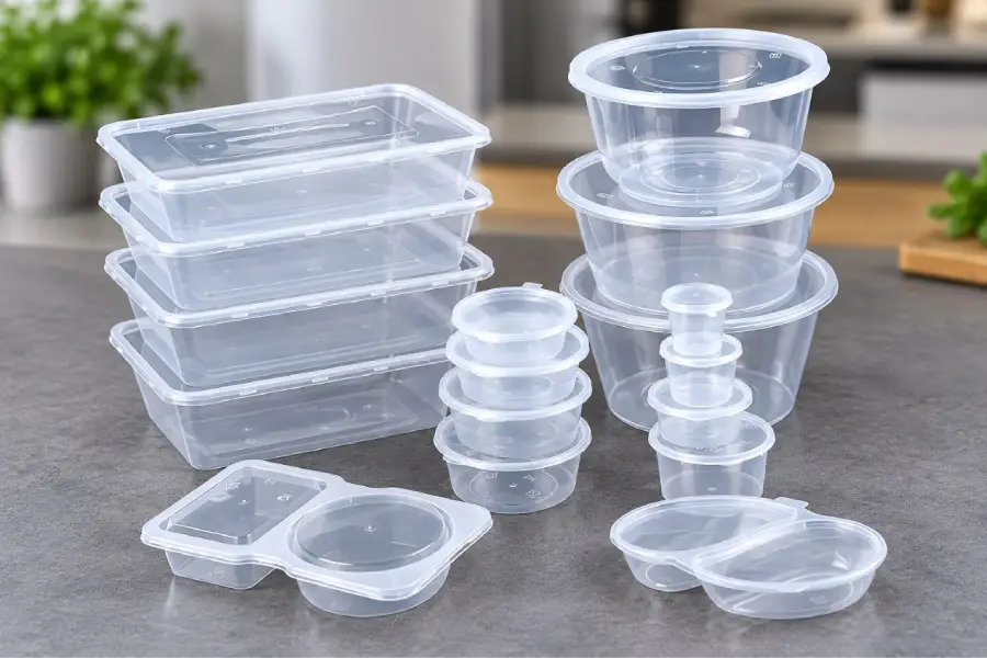
Thin-Wall Injection-Molded Part Examples
2. How Should Thin-Wall Injection-Molded Products Be Designed?
Thin-wall structures provide less design tolerance, so molding feasibility and part strength must be considered early in development.
1) Wall Thickness Design Principles
a.Keep wall thickness as uniform as possible; a wall-thickness variation of ≤25% is recommended. A large difference between the maximum and minimum wall thickness within the same part causes uneven cooling rates and can lead to Warpage, Sink Marks, and internal stress.
b.Minimum wall thickness varies by material. The following values can be used as references:
High-flow PP: recommended minimum safe wall thickness about 0.45 mm; trial-limit wall thickness about 0.30 mm.
ABS / PC-ABS: recommended minimum safe wall thickness about 0.60 mm; trial-limit wall thickness about 0.40 mm.
Thin-wall-grade PC: recommended minimum safe wall thickness about 0.70 mm; trial-limit wall thickness about 0.50 mm.
Glass-fiber-reinforced PBT: recommended minimum safe wall thickness about 0.75 mm; trial-limit wall thickness about 0.55 mm.
c.Use radiused transitions at internal corners. Sharp corners can cause melt hesitation and stress concentration, and thin-wall parts may crack from these locations under assembly loads.
2) Ribs and Bosses
Rib dimensions on thin-wall parts should be designed in relation to the main wall thickness:
- Rib thickness can be kept at ≤0.6 times the main wall thickness. Excessively tall ribs can trap air or cause incomplete filling; a rib-height-to-rib-thickness ratio of ≤3:1 can be used as a reference.
- When a Boss connects directly to a 0.6–0.8 mm thin wall, add a transition angle where appropriate. Core out the Boss root to reduce Sink Marks and uneven cooling caused by local thick sections.
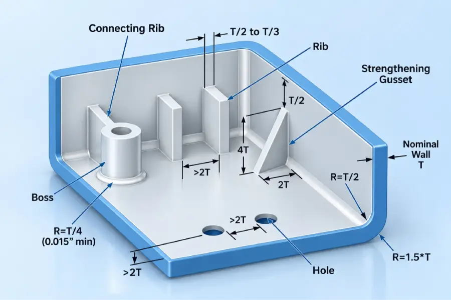
Reference Diagram for Rib and Boss Design in Plastic Parts
3) Gate, Runner, and Venting
Melt cools quickly in thin-wall molding. If the Gate is too small, it may freeze off early and restrict subsequent filling.
a.Pin Gate: For parts with a wall thickness of 0.6–1.0 mm, a Gate diameter of ≥0.8 mm can be used as a reference.
b.Side Gate: Gate thickness can be set at ≥0.7 × the product wall thickness.
c.For high-L/T structures, use multiple Gates to shorten Flow Length. With a single Gate, control the Flow Length.
d.Ultra-thin-wall products can use a Hot Runner to reduce cold material and Pressure Loss. For a Cold Runner, determine Runner diameter based on the material, Flow Length, and part size.
During high-speed thin-wall filling, inadequate venting can cause Burn Marks and Short Shots. Reference Vent depths are 0.015–0.025 mm for non-GF materials and 0.03–0.04 mm for GF materials. Place Vents at the Flow End and where Flow Fronts meet.
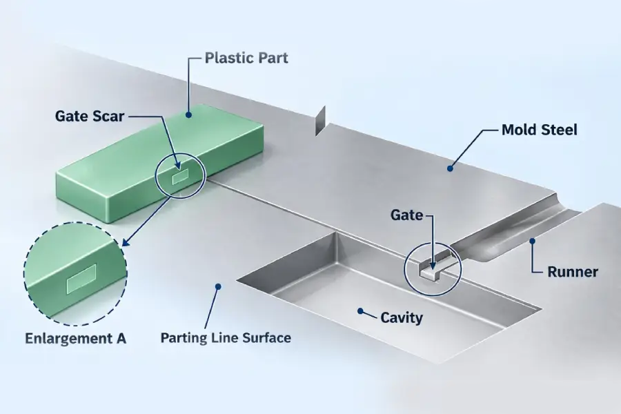
Gate, Runner, and Vent Structure Diagram
3. How Should Materials Be Selected for Thin-Wall Injection Molding?
The table below lists common material references for thin-wall injection molding. MFR values are provided for preliminary material comparison:
| Material | MFR Reference | Key Thin-Wall Molding Considerations |
| High-flow PP | 30–60 g/10 min | Rigidity and low-temperature performance |
| High-flow ABS | 25–40 g/10 min | Heat resistance and long Flow Length filling |
| PC-ABS | 22–35 g/10 min | Material viscosity and drying |
| Thin-wall-grade PC | 30 g/10 min or above | Drying, Melt Temperature, and Pressure Loss |
| GF-PBT | 20–30 g/10 min | Fiber Orientation and Warpage |
4. What Special Requirements Apply to Thin-Wall Injection Molds?
Thin-wall products have a narrow molding window. Mold design therefore requires targeted optimization of filling, venting, rigidity, and ejection.
1) Gate and Runner
If the Gate and Runner cross-sections are too small, Pressure Loss increases and the Flow End becomes more prone to Short Shot.
For products with a wall thickness of 0.6–1.0 mm, a Pin Gate diameter starting at about 0.8 mm can be used as a reference; Side Gate thickness can be about 70% of the product Wall Thickness.
2) Cavity Venting
Air Traps can easily form at the Flow End, Rib ends, and Flow Front meeting areas, causing Burn Marks, Short Shots, and Weld Lines. Place Vents at the actual last-fill locations. Use a Short-Shot Study or Moldflow to confirm the Flow Front before determining Vent locations.
Reference Vent depths are 0.015–0.025 mm for non-GF materials and 0.03–0.04 mm for GF materials.
3) Mold Rigidity
Insufficient mold rigidity under high pressure can cause Flash, dimensional deviation, and mold-plate deformation. As a reference, high-volume thin-wall molds can use NAK80 or S136-H steel at HRC52–56; clamping force can be sized at approximately 45–65 ton/100 cm² of projected area.
4) Ejection and Demolding
For thin wall parts, the rigidity is low and if using conventional ejection method, it may die with whitening, punch-through or deformation. Reduce concentrated loading at one point using blade ejectors, multi-point ejector or ejector blocks. For comparison, make the mold Draft Angle 1°-2° higher than thicker-walled parts; for less friction during demolding, use cavity polish of grade A2 or higher; for ultra-thin parts, demolding friction will be reduced by using air-assisted ejection, and demolding deformation can be prevented.
5. How Should the Thin-Wall Injection Molding Process Be Controlled?
Once the product, material, and mold designs have been determined, it is essential to define the molding window for the injection parameters. The following parameters can be taken as the first trial molding reference and further adjusted according to the Moldflow analysis and actual molding conditions.
High-flow PP: barrel temp. 200 to 230 C, mold temp. 40 to 55 C, Injection Speed high at 70 to 90%, Injection Pressure 80 to 120 bar and Holding Pressure 30 to 50 bar.
PC-ABS: Injection Speed high 65%~85%, Holding Pressure 40 bar~70 bar, Injection Pressure 100 bar~140 bar, Barrel temperature 230℃~260℃, Mold temperature 55℃~70℃.
Thin-wall PC: barrel temp. is 270 – 300 °C and mould temp. is 75 – 90 °C. Injection Speed is high (75 – 95 %), and Injection Pressure is 120 – 160 bar, and Holding Pressure is 50 – 80 bar.
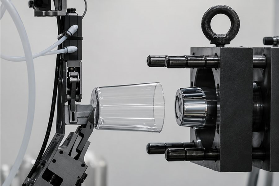
Thin-Wall Injection Molding Production
6. Advantages and Limitations of Thin-Wall Injection Molding
Thinning the walls saves material, reduces weight and decreases molding time, however, it also makes manufacturing more difficult. The pros and cons of the system are listed below:
1) Main Advantages of Thin-Wall Injection Molding
a.Reduced material usage: With a decrease in Wall Thickness the Part Weight also decreases. These material savings make a significant difference to high volume productions.
b. Cooling Time: Cooling time is greatly affected by wall thickness. Wall Thickness Reduction: Shorter Molding Cycle.
c. Lightweight products: Appropriate for packaging, consumer electronics, medical consumables and others with weight and size constraints.
d. It is applicable for small and compact structures: Thin Housing, Cover and Internal Structures can be made in limited space.
2) Main Limitations of Thin-Wall Injection Molding
The narrower the Process Window, the thinner the Wall Thickness. Short Shot or Flash can be caused by changes in viscosity of materials, Mold Temperature, Injection Speed, Gate Pressure Loss and Vent conditions. The large thin-wall parts are also prone to Warpage, Weld Lines and Ejection Deformation.
7. Which Products Are Suitable for Thin-Wall Injection Molding?
Food and consumer packaging: food containers, cups, lids, thin-wall containers and disposable packaging.
Medical and Lab Disposables: Sample Cups, Cartridge Housings, Pipette associated Parts, Reagent Consumables.
Consumer electronics and equipment housings: Housing, Cover, Internal structural parts.
Electrical Housings: Electrical Cover, Protective Enclosure.
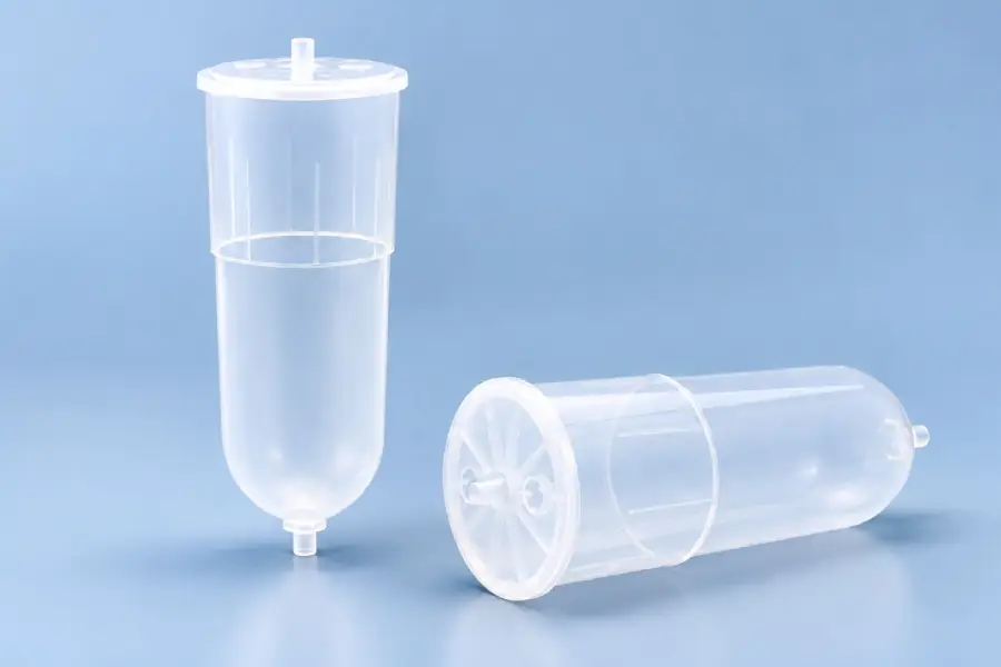
Medical Thin-Wall Injection-Molded Reservoir Part
8. Common Thin-Wall Injection Molding Problems and Troubleshooting
If defects are found in thin-wall parts, determine the cause by referring to the location of the defect and the condition of the filling. The following is a list of common problems and troubleshooting tips that can be used as reference:
1) Short Shot / Incomplete Filling
Symptom: Areas far from the Gate, local thin sections, Rib ends, or the Flow End do not fill completely.
Possible causes: Excessive L/T, local Flow Restriction, excess Gate or Runner Pressure Loss, insufficient venting, low Melt/Mold Temp., or too slow of injection speed or pressure available.
Troubleshooting: Run a Short-Shot Study to watch the Flow Front. Look at Gate, Runner, local Wall Thickness and Flow End venting. Once the mold structure and the part structure are OK, the Melt Temperature, Mold Temperature, Injection Speed and Injection Pressure are adjusted, respectively. If the Short Shot is at the far end (consistently), re-check the location of the Gate and the actual L/T.
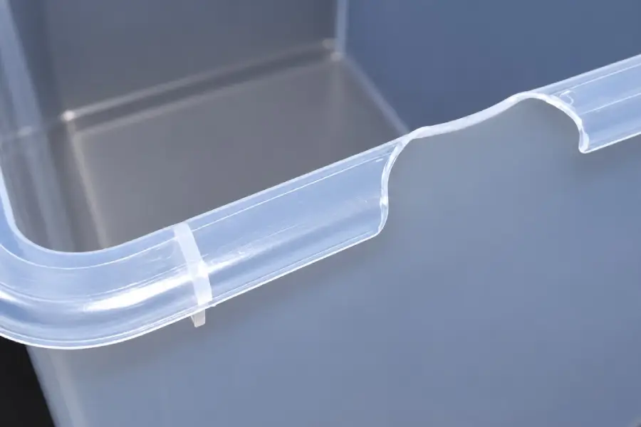
Injection Molding Short Shot
2) Flash
Symptom: Thin Flash appears at the Parting Line, Insert, or local mating areas.
Possible reasons: Excessive Cavity Pressure, late V/P Transfer, Insufficient Clamping Force, Poor Parting Line fit, or Elastic Deformation of the Molding Parts.
Troubleshooting: If Flash always shows up at the same spot, examine local support and mold fit. If it is seen in multiple locations simultaneously, inspect Peak Pressure, V/P Transfer and clamping force.
3) Warpage
The symptom is that, after demolding, large flat areas warp, edges lift or dimensions change.
These are typical causes of the problem: Asymmetric Wall Thickness, Uneven Cooling, Fiber Orientation, High Ejection Temperature or low structural rigidity.
Troubleshooting: Check the direction of deformation with the Flow Direction, Rib layout and Cooling Circuit. In the case of GF materials, inspect Fiber Orientation, and then modify the Rib design, local cross-section, or Gate location.
4) Burn Marks / Air Traps
Burn Marks are either black or brown and are found at the Flow End, Rib ends or in the vicinity of the Weld Lines, sometimes in combination with a Short Shot.
Common causes: Air Traps, insufficient or obstructed Vents, local geometry that creates gas traps, and too high of an Injection Speed towards the end of fill.
Troubleshooting: Check the Last Fill Location and use a Short-Shot to check the Flow Front. Clean and/or turn on Vents, and adjust Gate or Flow Path as needed.
5) Ejection Deformation
The symptom is that the part is all right in the mold but dents, whitening from ejectors, bending or permanent deformation occur after the mold is ejected.
Common causes: Lack of a firm enough part, too much Ejection Force, too shallow a Draft Angle, too tight a Core grip or a high Ejection Temperature.
Trouble shooting: Determine if the deformation is associated with the location of the Ejector Pin(s) and Core gripping area(s). Adjust or enlarge ejection area and add a Stripper if needed. After that, look at the parameters Draft Angle, surface condition and Cooling Time.
9. Summary
Thin wall injection molding is extensively used in food packaging, medical consumables, automotive and industrial equipment housings, and consumer-electronics housings. It can minimize the consumption of plastics and the weight of products, as well as shorten cooling and molding cycles. Hollyplasticparts offers thin-wall product structural design, material selection, mold development, process validation and mass production service. We assess mouldability of the products and work out the crucial engineering aspects. Call us for technical assistance if you are developing any consumer, medical consumable, packaging or industrial components.