The design of an injection mold affects how a plastic part is filled, cooled, vented, and ejected. This article explains the basics of injection mold design and shows what makes a mold stable, production-ready, and capable of delivering consistent part quality.
1. What Is Injection Mold Design?
The design of an injection mold is a process of making plans on how a mold will create a plastic component in a measured and reproducible manner. It is not merely that of moulding the hollow. It also involves the flow of molten plastic into the mold, the escape of the trapped air out of the mold, the removal of heat, the extraction of the part after cooling is done, and the maintenance of the accuracy of the mold at the production conditions.
Mold design in the real world impacts the quality of the parts, consistency of the cycle, complexity of the tooling, maintenance requirements, and the overall dependability of the production process. A mold can appear right on the paper and cause problems in the process of manufacturing. The filling direction should not be ineffective, as it will not fill the part evenly. Failure to plan the cooling of a part may lead to warping of the part or excessive time to solidify it. In the event that venting is not taken into account at an early stage, the gas traps and surface defects can be observed. In case of unbalanced ejection, the part can be stuck, scratched, or distorted when released. This is the reason why mold design is a decision of the system, but not an easy task of making shapes.
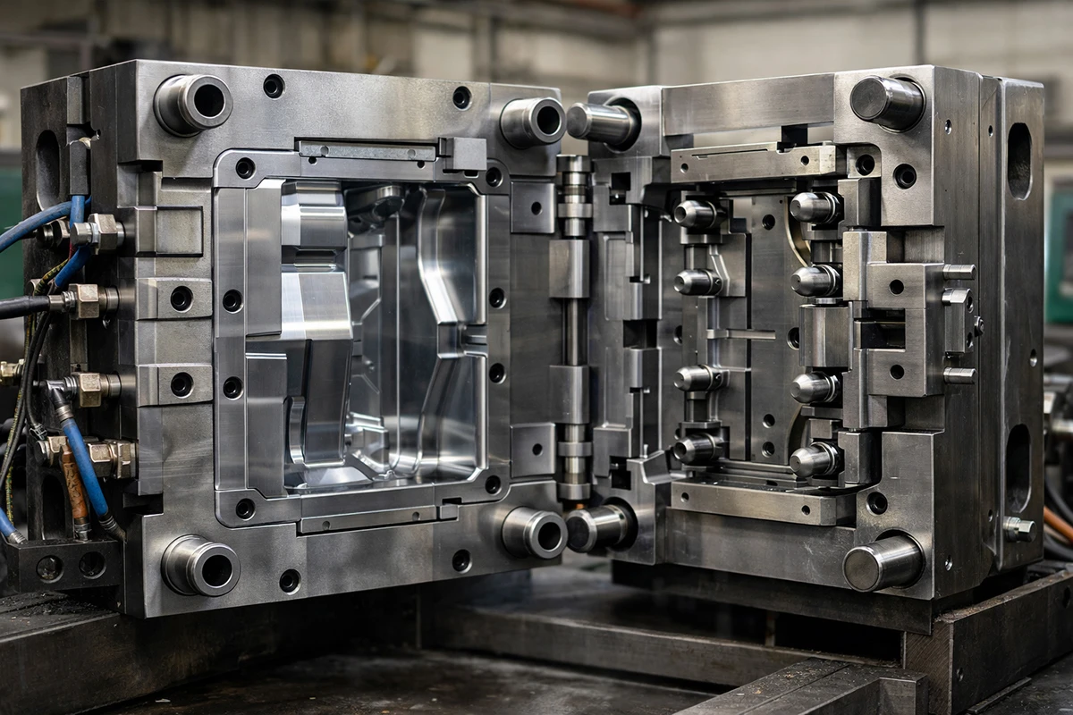
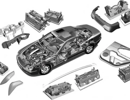
2. The Core Elements of an Injection Mold
An injection mold is not simply a tool for forming. It is a production system comprising a number of functional components that need to work in unison during production. There are aspects that determine the part, aspects that determine the flow of the melt into the cavity, aspects that determine heat extraction, and aspects that assist in the release and stability of the mold. When a single area is weak, then the mold can continue to experience issues with filling, cooling, ejection, dimensional control, or long-term repeatability.
This is why it is better to be familiar with the key elements of the molds first and then examine the finer details of design concepts. The following table demonstrates the simplified role of all the core components of the mold system.
| Mold Element | Basic Function |
| Core and cavity | Form the shape of the part |
| Parting line | Define where the mold opens and separates |
| Feed system | Deliver molten plastic into the cavity |
| Cooling system | Remove heat from the mold and part |
| Venting features | Let trapped air and gas escape |
| Ejection system | Release the part after cooling |
| Guide and support elements | Keep the mold aligned and stable |
3. Key Principles Every Engineer Should Know
It is not enough to know the key elements of the moulds. The greater question is the way they should be structured. A mold must not merely be able to make a single sample that can be acceptable. It must also be capable of production application with stable filling, controlled cooling, dependable ejection, and maintenance that can be controlled. It is the reason why the following principles are relevant.
1) Principle 1: The Parting Line Should Be Planned Early
Parting line is the line along which the mold opens; it ought to be designed at an early stage of design. The decision has impacts on appearance, direction of mold opening, conditions of shut-off, machining difficulty, and risk of flash.
An ineffective parting line normally generates unnecessary issues. It can cause some spots on significant surfaces. It can also lead to poor shut-off locations, which are more difficult to fit and also flash-prone in the course of production. In other instances, a complicated parting line will increase the cost of a mold to be constructed and difficult to maintain, yet it does not enhance the functionality of the part.
The natural and easy parting line is preferable in most of the projects. It can be machined more easily, aligned more easily, and maintained more easily. The parting line complexity usually indicates increased tooling risk, more fitting, and is a more probable cause of delays during mold tryout and correction, as far as the project decision is concerned.
2) Principle 2: Draft Angle Is Essential for Reliable Demolding
The small taper on the vertical surfaces is known as the draft angle to allow the part to eject out of the mold with ease. The part may stick to the steel in case of a lack of draft during ejection.
This may cause scratches, drag marks, stress whitening, sticking, or damage to parts. The danger is increased on deep walls, rough surfaces, and those with huge contact areas. Textured surfaces tend to require higher draft since the release friction is higher when the surface is textured.
Practically, a draft is not a secondary aspect that should be considered as a design requirement. Good draft assists in securing the part surface, ejection force is minimized, and stability of production is enhanced. In terms of project planning, a weak draft normally implies the existence of a greater probability of cosmetic flaws, handwork, and ping pong in the course of sampling.
3) Principle 3: Wall Thickness Should Be as Uniform as Possible
Wall thickness implies the thickness of the plastic in the part. In injection molding, the thickness of the wall must be as even as possible since more balanced areas are filled, packed, and cooled more easily.
In the case of a thick section, it cools at a slower rate. This would result in sink marks, voids, longer cooling time, and non-uniform shrinkage. Internal stress and warpage are more probable when there is too much variation in the wall thickness.
This does not imply that all the parts should be identical in the thickness of the walls throughout. There are a lot of sections that require ribs, bosses, and reinforced sections. The trick lies in the fact that it is important to manage the thickness changes and prevent the unnecessary heavy parts. Business-wise, the design of walls has an impact on the part consistency and cycle time, and therefore it has a direct impact on the production efficiency, reject risk, and the unit cost.
4) Principle 4: Material Behavior Must Be Considered from the Start
The behavior of the material used is known as material behavior, where the behavior of the chosen plastic flow, shrinkage, cooling, heating, and pressure reactiveness during the molding process. The design of the mold must not be done without considering the material, since various plastics are not the same in the mold.
The most evident example is shrinkage. Shrinkage of different materials is not the same, and this influences the size of the cavity and the end part. It is also important for the flow behavior. There are plastics that fill the long flow paths more easily, as compared to those that require more attention to the placement of the gates and walls.
Other material properties may also have an effect on mold design. The glass fiber is capable of altering the shrinkage behavior, dimensional behavior, and wear on the mold surfaces. The viscosity influences the filling pressure and the behavior of the gates. Resistance to heat influences the cooling anticipations and stability of the processes. Unless the behavior of the materials is taken into account at the first stage, it becomes harder and more costly to rectify later. This can also be used in supplier discussions as a good indication of the maturity of a design, since the behaviour of a real production material should already be represented by the concept of its mold.
5) Principle 5: Gate Location Should Support Balanced Filling
The entrance through which molten plastic gets into the cavity is called the gate. The location of that entry point on the part is referred to as the gate location. This decision has a major effect on filling quality.
The gate is not to be selected due to the fact that it permits the entry of material into the cavity. It must also accommodate a sensible flow direction, tolerable pressure drop, effective packing, and consistent part quality. In case the position of the gate is weak, the part can exhibit weld lines, lumpy shrinkage, visible marks, deformation, or weak filling of hard-to-reach parts.
An improved positioning of the gate would typically allow easier filling and a more balanced packing. It is also able to minimize cosmetic risk and enhance dimensional stability. In project decisions, it is not only a technical consideration whether the location of the gate is important or not. It may influence the degree of the process adjustment in the future, the stability of the quality of the part, and whether the offered mold concept is actually production-ready.
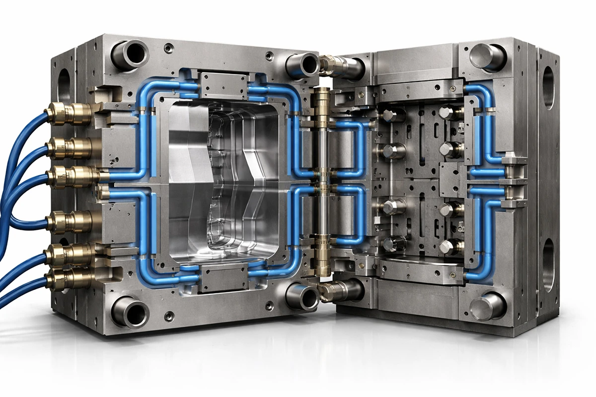
6) Principle 6: Cooling Design Must Support Both Quality and Efficiency
Cooling design refers to the format applied in eliminating heat in the mold and part in a controlled manner. It happens to be one of the most critical areas of the performance of molds, as it influences the quality and efficiency.
In case of uneven cooling, various parts of the part will shrink at varying rates. This can easily cause warpage, dimensional instability, or internal stress. In cases where filling is acceptable, it is still possible to have poor cooling of the final part.
Cycle time is also directly proportional to cooling. In most molding operations, cooling occupies a major portion of the entire cycle. It implies that the cooling efficiency is highly influential on output and the cost of production. Decision-wise, cooling design is arguably one of the most straightforward connections between the design of the mold and manufacturing economics, as it has an impact on the productivity, dimensional stability, and the long-term capability of the consistent running of the mold.
7) Principle 7: Venting Must Be Designed as a Functional Requirement
The process of allowing the cavity to be filled with air and gas is called venting. This is an essential prerequisite in designing the mold since the air that is already present in the mold should exit as the melt flows into it.
When there is poor venting, the air trapped does not flow easily, and this presents an issue of molding. These issues may be short shots, burn marks, gas traps, unstable filling, and surface defects. What appears to be a material problem or machine problem on most occasions is a venting problem within the mold.
Ventilation aids in a more fluent flow and minimizes defects to be seen. It must be considered as a normal feature of design and not a correction made late, when some trials have shown that there are issues. In the case of project control, when there is poor venting, it will be characterized by more trial-and-error and more debugging when sampling, and a greater likelihood of early production not running as smoothly as it was planned.
8) Principle 8: Ejection Must Be Balanced and Reliable
The expelling of the cooled portion out of the mold is referred to as ejection. Ejection needs to be consistent and dependable in design. The part must not just come out. It should not be discharged distorted, damaged on the surface, or unsteady.
Harmful layout of ejectors may lead to a concentration of forces in a small number of places. This may result in deformation, drag marks, stress whitening, or sticking. The danger usually lies in the thin parts, deep parts, and cosmetic parts. Others are also narrowing down to core features, and that increases the challenge of release.
A proper ejection system takes into consideration the location of the part once it has been opened, the amount of force required, and the distribution of the force. Quality ejection is important since poorly designed ejection results in cosmetic flaws, unreliable manufacturing, and increased machine handover in the factory. Project-wise, that normally translates to increased work, additional time, and decreased predictability.
9) Principle 9: The Mold Must Stay Accurate and Stable in Production
Mold stability implies that the mold can retain its alignment, size, and working state in repeated production cycles. The tool is put under pressure, heat, clamping force, and wear, and undergoes repeated opening and closing during molding.
When the structure of the mold is weak, the alignment can change, and the areas where it needs to be shut off can be worn out more quickly. This may result in flash, unstable dimensions, low repeatability, and reduced life of the mold. These issues might not be evident in the initial sample run, but they tend to be more evident in extended production.
An end product mold should be stable in actual operating conditions and not just during ideal trial conditions. The success of the sample in the early stage does not necessarily imply that the mold will be stable in mass production. In the case of project decisions, it is relevant since the long-term stability influences the delivery reliability, the frequency of maintenance, and the actual cost of the tool ownership.
10) Principle 10: The Mold Must Be Practical to Build, Maintain, and Run
Practical mold design implies that the mold must be functional in actual manufacturing, and not just in design software. An idea might appear right on paper and still be hard to machine, hard to put together, hard to maintain, or hard to run reliably.
Due to the very complicated geometry, machining can be made difficult. Maintenance in tight internal places may become difficult. The features that are overdesigned may cause the cost of tooling, but they do not address an actual production issue. A good design must also be checked on buildability, serviceability, and practicability at operation, as well as for simple operation.
The best mold in most of the projects is not necessarily the most complex. It is the one that attains the demanded part quality, having a structure that is clear, manageable, and stable. In the case of project planning and evaluation of suppliers, this frequently shows whether the design methodology is sensible, cost-conscious, and can be used in long-term production of the product, not just short-term sampling.
4. A Simple Review Checklist for Basic Mold Design
The idea of the entire system should be reconsidered before a mold design passes to the next phase. This is where the idea is not to introduce further complexity. This is aimed at ensuring that the principal design choices are already reasonable to mould, manufacture, stability, and usage durability.
In case the fundamental concept remains contingent upon too many assumptions, the mold is typically not yet prepared. In most projects, it is much easier and cheaper to rectify such problems in the design than when the mold has already been constructed.
| Review Area | What to Check |
| Core and cavity | Is the part geometry formed correctly in the mold? |
| Gate and runner | Is the filling path reasonable and balanced? |
| Cooling | Can heat be removed evenly across the mold? |
| Venting | Is there a clear path for trapped air to escape? |
| Ejection | Can the part be released safely after cooling? |
| Parting line and alignment | Can the mold stay stable and accurate in production? |
5. Common Questions Engineers Have About Injection Mold Design
The following are some questions that engineers have about injection mold design.
(1) What are the Factors to Be the Most significant when designing an Injection Mold?
Part geometry, material behavior, path to filling, balance of cooling, venting, ejection, and stability of the mold are the most important variables, which are usually considered. These aspects need to be considered as a whole and not individually. A mold can do well in one place and fail in production, yet another place is poor. In reality, good mold design is not a process of maximizing an individual feature. It is about maintaining the entire system in balance and stability.
(2) Why is it so Important to the Mold Design to have the Gate in the Right Place?
The issue of the location of the gate is that it influences the way molten plastic gets in and flows through the cavity. It affects loss of pressure, position of the weld line, behavior of the packing, cosmetic looks, and deformation risk. Not all gates are good gates; a gate that only allows the part to fill is not a good one. An improved position of a gate tends to enhance the stability of filling and minimize the time spent on repetitive adjustment of processes used in sampling and production.
(3) What Can Cooling Design Do to Part Quality and Cycle Stability?
Cooling design has an impact on the quality of the part and the efficiency of production. Without even distribution of heat, there is a risk of parts shrinking unevenly, becoming warped, experiencing internal stress, or having unstable dimensions. The cycle time is also influenced by cooling since, in most cases, it consumes a significant proportion of the molding cycle. An effective cooling design aids in making the mold operate at a steady rate and bearable production in the long run.
(4) Why Does a Low Venting of the Formation Cause Filling Problems and Surface Defects?
Bad venting entraps the air and gases within the cavity during filling. In case the trapped air is not able to escape, it opposes the flow of melting and causes difficulties in molding. These can be short shots, burns, gas traps, unstable fillings, and surface defects. The problem of venting is usually overlooked due to the fact that it can be taken as a material or process problem at first sight. As a matter of fact, they tend to be simple design issues of moulds.
(5) Why do some of the plastic parts get lodged in the mold in the cooled-down form?
This mostly occurs due to the fact that the part will clamp the steel so hard after the shrinkage. The most common causes are a lack of draft, wrong ejection pattern, deep core characteristics, and no shrinkage or friction on the surface. Drag marks, whitening, scratches, or deformed parts during release can also be observed in a part that remains stuck in the mold. This usually translates into increased handwork in manufacturing, reduced quality, and the part is prone to damage.
(6) What Could You Do to know whether a Mold Design is prepared to be made?
The further a mold design is from production-ready, the more the main design questions can be answered before machining starts. It should be mouldable, the behavior of the material should be known, and the filling, cooling, venting, and ejection process should be checked. The mold is also supposed to be stable enough to be reproduced again, and easy to construct and maintain. When the number of assumptions to be made is too high, the tooling risk is typically high.
6. Conclusion
The fundamentals of injection mold design all boil down to several key objectives: to shape the part right, to fill it in a controlled manner, to cool it uniformly, to vent it so that it vents, and to eject it in a controlled fashion. Mastering these fundamentals makes it much easier to ensure your project sustains stable production and steady quality. If you are developing a plastic injection-molded part, an early DFM and mold design review can help avoid costly tooling mistakes.
Leave A Comment