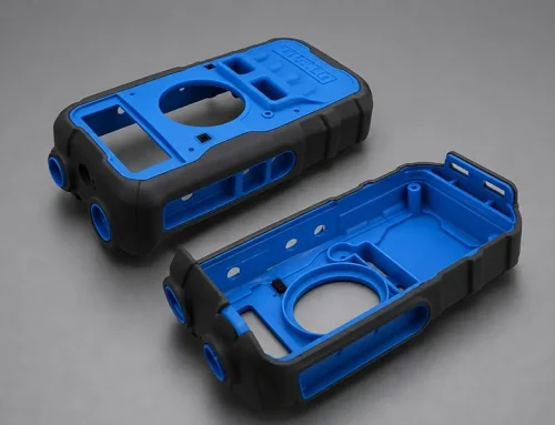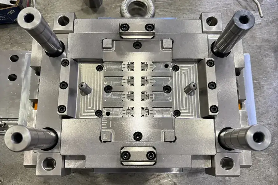
Direct function integration of metal or ceramic parts in plastic structure: Insert molding. It can be used to create a metal, ceramic or any other functional parts as a single functional unit with plastic, thereby eliminating the need to assemble the parts and improving the accuracy and reliability of the insert’s positioning.
This article begins by the principles of insert molding and then introduces the process flow, materials used and important design points. It also examines the various common applications found in automotive, electronics, medical, and industrial products, and discusses common molding defects and troubleshooting strategies for assist engineers looking to better evaluate insert-molded products.
1. What Is Insert Molding?
First, understand the basic molding logic of insert molding and how its production method differs from conventional injection molding.
1) How Insert Molding Works
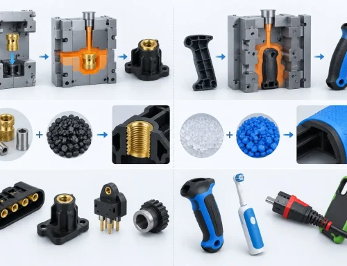
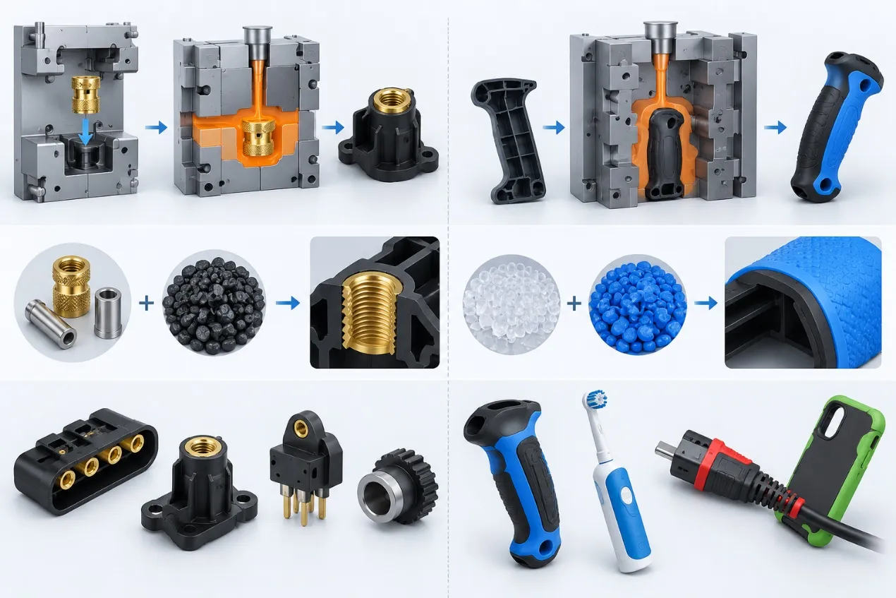
Insert molding involves inserting a pre-formed metal or other component into an injection mold prior to the injection of molten plastic. Plastic encapsulates and holds the first piece together to form a single piece. The common process steps are: Metal Insert, Mold Positioning, Plastic Injection, Plastic Encapsulation, Cooling and Plastic-Metal Integrated Part.
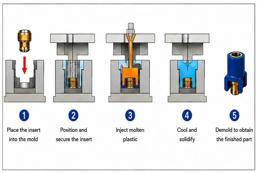
Basic Principle of Insert Molding
2) Difference Between Insert Molding and Conventional Injection Molding
Traditional injection molding involves four main stages: filling, packing, cooling, and demolding. Before molding begins, any inserts—such as metal, ceramic, or magnets—must be positioned in the mold. Engineers also need to consider the insert position, how the melt may affect it, stress at the interface, differences in shrinkage between materials, and mechanical locking.
2. Advantages and Limitations of Insert Molding
Insert molding integrates structure and function during the molding process. Its main advantages and limitations are as follows:
1) Main Advantages of Insert Molding
a.Assemblage downstream process reduction: The nuts, terminals, magnets, and other components can be attached to the plastic during the injection molding process, thereby avoiding press fit, gluing, screw fitting, and other such assembly steps.
b.Insert security: Insertion through knurling, grooves, undercuts, and holes results in mechanical interlocking, increasing resistance to rotation and removal of inserts.
c.Molded integration: A single piece can serve more than one purpose like conduction, insulation, magnetic coupling, fastening, or load-bearing.
d.Assembly tolerances reduction: Through mold locating, it is possible to reduce the tolerance of insert position due to manual assembly done subsequently.
2) Limitations of Insert Molding
a.Additional mould feature of positioning, stopping and sealing inserts: More complicated moulding operations and tooling with positioning, stopping and sealing moulding inserts.More complex tooling and production: Positioning, stopping and sealing moulding inserts; moulding production requires positioning and inspection.
b.Insert displacement risk: Direct melt impact can cause displacement or tilting of the insert, and can bend long slender inserts.
c.Interface stress: Materials like plastic, metal, or ceramic have different expansion and contraction properties, leading to the development of residual stress around the insert.
d.For some inserts: Magnets, some surface-treated parts and some other temperature-sensitive parts, the limits of molding temperature should be evaluated to see how it will affect the performance of the part.
3. Insert Molding Process
Insert molding quality depends on the injection parameters, insert condition, positioning method, and post-molding inspection. In practice, complete process control usually starts before the insert enters the mold.
1) Insert Preparation and Pretreatment
The dimensions, appearance, knurls, grooves, threads and surface condition of the insert should be checked to ensure the quality of the molding products. Plastic encapsulation problems can occur, leading to the formation of interface bubbles and voids, due to oil, cutting fluid and moisture on the surface of the insert. Depending on the condition of the surface, metal inserts can be degreased, cleaned and dried. Zinc or nickel plating can be used to achieve special surface properties or corrosion resistance.
2) Insert Positioning and Mold Installation
Locate the insert into the set position within the mold and secure it with locating pins, stop shoulders, cores or pressure blocks. Include auxiliary positioning for long inserts, terminals and structures subjected to high melt impact. Before closing the mold, ensure that the insert is completely in place, and that it is oriented, flat and located in the mold.
3) Plastic Injection Molding Process
Once the mold is closed the molten plastic flows around the insert and into the cavity. If there are features such as Groove, Undercut, or Knurl in the insert, the plastic will fill these features and a mechanical lock will be created after cooling. Pre-dry hygroscopic materials as per requirement of the materials for molding. Additionally during filling, inspect venting around insert, textured features for filling, and short fill and trapped air at flow end.
4) Demolding and Quality Inspection
Try to not focus the ejection force on thin areas of the mold around the insert during demolding. Following ejection, verify insert position, plastic encapsulation, cracks, flash and voids. Verify the mechanical locking performance of inserts with anti-rotation or pull out requirements with Torque-Out and Pull-Out tests.
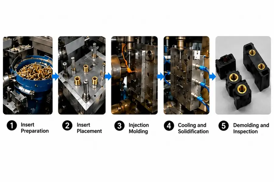
Insert Molding Process Flow
4. Common Insert Molding Materials
Insert molding combines different materials. Common options include:
1) Common Insert Materials
Brass/Copper Inserts: Conductive, often used for conductive terminals, connectors and threaded inserts.
Carbon Steel/Stainless Steel Inserts: These are also strong and endure wear, and are utilized in nuts, bushings, fasteners and load-bearing structures. Alternatively, stainless steel can be used where corrosion resistance is required.
Magnet Inserts: Magnetic attachment, positioning and sensing structures.
Ceramic Inserts: These are relatively brittle and offer a combination of electrical insulation, heat resistance and corrosion resistance. The position and melt effect are special points to be considered for molding.
2) Common Plastic Materials
PA6/PA66: Good strength and toughness, application for automotive, electrical and structural insert-molded parts. They are moisture absorbent, and need to be dried prior to molding.
PBT and Glass-Fiber-Reinforced PBT: Good dimensional stability and electrical insulation; commonly used for connectors and electrical/electronic components.
PC/PC-ABS: Good impact resistance; suitable for electronic housings and structural parts. PC is sensitive to stress and certain chemicals, so residual stress around inserts requires attention.
PPS: Excellent high-temperature resistance, high chemical resistance and dimensional stability, applicable to insert-molded parts such as the automotive, electrical and high-temperature industry.
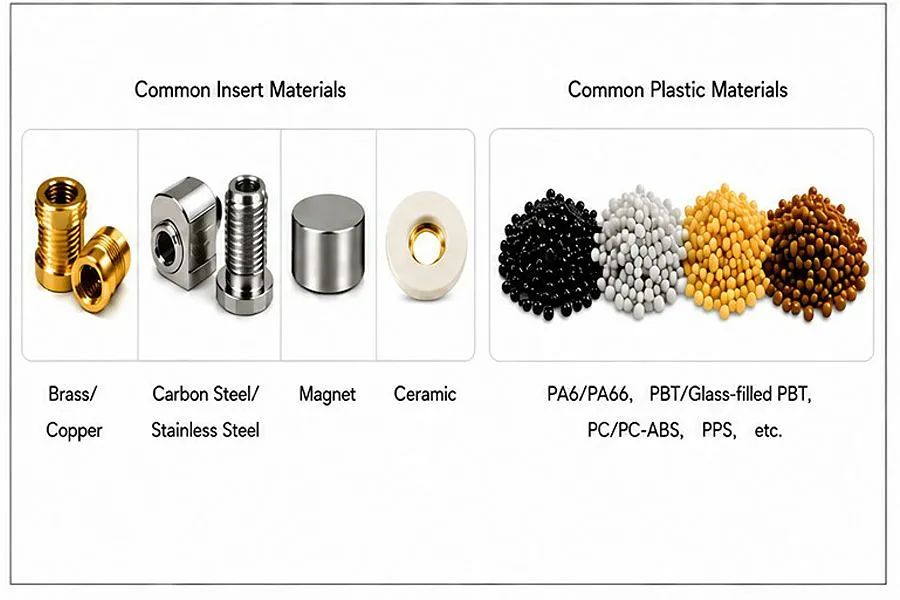
Common Insert Molding Materials
3) Compatibility Between Plastic and Inserts
Thermal expansion and shrinkage: The thermal expansion and shrinkage of plastics, metals and ceramics are different. As the plastic cools it shrinks around the insert.
Matching with plastic moulding temperature: Match with the temperature range required by magnets, coatings, etc., in the machine.
5. Key Design Points for Insert Molding
Most metal insert-molded parts rely mainly on plastic shrink-fit around the insert and mechanical locking created by the insert’s external features.
1) Plastic Wall Thickness and Stress-Relief Design
If too thin, the plastic wall around an insert is easy to sustain the stress and might lead to a radial crack due to cooling shrinkage. As a guideline, leave plastic encapsulation at 1.0 mm or more around metal inserts, and possibly thicker for PC, glass-fiber-reinforced materials and others. Keep the wall thickness around the insert as uniform as possible.A local wall-thickness variation of up to 20% may be adopted as a reference, to minimize the differential cooling shrinkage resulting from sudden changes in wall thickness.
To allow plastic shrinkage, add a stress relief groove around the insert when the structure is constrained. Provide fillets at sharp insert corners to minimise stress concentration.
2) Anti-Rotation and Pull-Out Prevention Design
Smooth cylindrical inserts offer little mechanical engagement and are vulnerable to rotation and/or removal when subjected to screw tightening torque, axial load or vibration. Common anti-rotation and pull out features:
a.Diamond or straight knurl: Provides increased circumferential mechanical engagement between the insert and plastic; good for nuts and threaded inserts.
b.D-shaped flat: designed to avoid rotation of the insert, particularly used in situations where the insert needs to be positioned in a certain direction, such as sensors and automotive electronic controls.
c.Side through-hole: Plastic locking through hole, prevents axial pull-out and rotation.
d.Annular undercut groove: Increases axial mechanical locking and improves insert pull-out resistance.
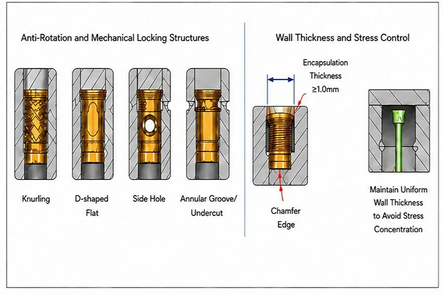
Anti-Rotation, Pull-Out Prevention, and Encapsulation Thickness Design
3) Gate and Runner Layout Design
When the gate directly faces a suspended thin wall, the side of a long insert, a slender pin, or a terminal, high-speed melt impact can shift, bend, or wash the insert out of position. Side gates and fan gates can feed from the side of the insert and reduce direct impact from the melt front.
4) Venting and Cooling System Design
The risk of creating voids, burning or incomplete local encapsulation are easily introduced with the insertion of grooves, knurls, steps, and melt meeting points.
Vent at flow ends behind the insert, at the meeting points of the melts and in dead corners where air may be trapped.
Place cooling channels in a satisfactory location around the insert and keep a proper distance from the cavity in order to cool the plastic around the insert evenly.
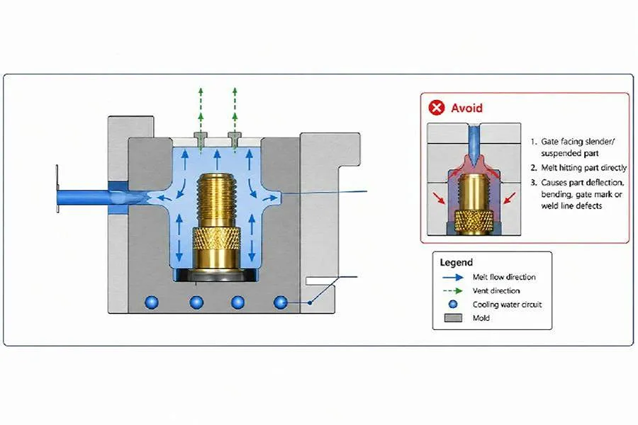
Gate, Melt Flow, Venting, and Cooling
5) Insert Layout Boundary
If an insert is placed near the product edge or near the thin-wall regions, the outer plastic part of the insert remaining is small and is at greater risk of cracking, break off or local deformation. A reference distance from the insert edge to the product edge is at least 1.5 times the thickness of the encapsulation wall.
6. Common Applications of Insert Molding
Insert molding is suitable for products that integrate a plastic structure with metal or other functional components. Common applications include:
1) Automotive Components
Automotive sensor housings, electrical-control terminals, fastening nuts and harness insulation are among the applications for insert molding. It’s good for electrical, fastening and structural connections to copper, brass or steel inserts with plastics such as PBT, PA and PPS.
2) Electronic Product Components
Insert molding is used to attach metal parts to plastic devices such as mobile phones and electronic devices with conductive terminals, connectors or internal charger components.
3) Medical Device Parts
Medical test connectors, instrument insulation components, and some conductive components can combine metal or ceramic inserts with engineering plastics.
4) Industrial Equipment and Consumer Products
Insert molding can be applied to the insertion for an industrial control housing, sensor bracket, smart home housing, magnetic function parts, and plastic parts for fixing appliances.
7. Common Insert Molding Problems and Solutions
Insert molding defects are typically related to positioning, flow, material shrink and bonding of the interface. If the problem arises, troubleshoot it systematically, according to the defect location and the time when the defect is found.
1) Insert Shift, Floating, Washout, or Deformation
The symptom is the insert is off-center, there are long insert bends or there is an unequal thickness of plastic around the insert.
Common causes: Gate will directly affect the insert; Initial injection speed is set too fast; The rigidity of the positioning structure is not sufficient; The clearance between the insert and the positioning feature is too large.
Solution: Reduce the initial injection speed and determine if the displacement of the insert is reduced as the melt impact force is reduced; determine if the melt flow direction and the location of the gate will hit a weak area of the insert; check locate pins and stop features; check the actual insert fit clearance. For products with multiple cavities, review the filling sequence and pressure distribution in each cavity.
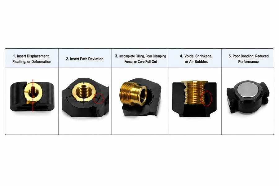
Common Defects
2) Radial Cracking Around the Insert
Symptom: Cracks occur in the molded or hot test section around the insert, on the radial direction.
Common causes: shrinkage of the plastic and metal, not enough plastic around the insert, stress concentration at sharp corners.
Solution: Measure the actual thickness of the plastic around the insert, sharp corners, crack initiation site; compare the condition of the cracks after molding, after storage, and after tightening the screw; and distinguish the molding residual stress from the assembly load.
3) Insert Slippage, Insufficient Torque, or Axial Pull-Out
Problem: The insert does not remain secured during tightening with a screw, it pulls out during a pull-out test or it is loose after vibration.
Common causes—No anti-rotation or pull-out and/or short fill or voids in grooves.
Solution: Check knurls, flats, through holes and other anti-rotation features if the anti-rotation performance isn’t good enough. If pull out resistance is not considered to be satisfactory, examine the annular grooves, undercuts, flanges and effective embedment length. Cut the sample to make sure that all the plastic goes into the knurls, grooves and undercuts and then check venting, filling and packing conditions.
4) Incomplete Encapsulation or Voids at the Insert-Plastic Interface
Symptom: If a section is cut, there is void or partial encapsulating between the insert and plastic.
Common causes: Resin moisture, oil contamination on the insert surface, trapped air in insert corners, lack of resin filling in grooves and knurled areas.
Solution: Inspect resin drying, and clean surface; Section the sample to verify void area. If voids collect at the ends of the flow, grooves or behind the insert, examine venting. Check the gate, filling process and filling pressure if there are still unfilled textured features.
5) Magnet Insert Demagnetization or Performance Loss
Symptom: Magnet strength decreases after injection molding.
Common causes: Injection moulding temperature of the magnet is above the safe operating temperature.
Solution: Check the Magnet Grade, Operating Temperature Range, and Irreversible Temperature Loss Range; Check Melt Temperature, Mold Temperature, and Magnet Actual Thermal Exposure Time in the Cavity. If the molding temperature for the material is incompatible with the magnet’s temperature, change the grade of the magnet, plastic material or molding solution.
8. Conclusion
Insert molding maintains the plastic and insert firmly connected during the entire service life of the product when it has the appropriate structure, materials and molding solution. According to the user’s needs, hollyplasticparts can provide insert molding process evaluation, mold designing, and injection molding mass production support, and optimize the structure of the parts to reduce the risk of mass production. Please give us a call to talk about your project needs.