What Mistake You Should Avoid When Injection Molding?
Like any manufacturing process, injection molding has its advantages and disadvantages. Some parts are easier to shape than others, and if you don’t know what you are doing, things will go wrong very quickly.
For novices who are trying injection molding parts for the first time, even for experienced engineers who usually use other processes, it is easy to fall into certain traps, which can cause parts to become weak, unsightly or deformed.
5 common injection molding mistakes is presented in this article, it also offers suggestions on ways to avoid them.
1. Change Wall thickness
Unlike CNC machined or 3D printed parts, they can come in many forms. Plastic injection molded parts generally look the same: thin objects, shell-like in shape, with no deep areas of solid material.
This is because injection molding works in this way. When the mold is filled with liquid materials, these materials must be cooled into a solid; If some areas cool faster than others, the colder areas will solidify and shrink before other areas, creating stress and causing parts to warp.
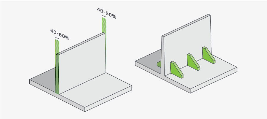
The way to avoid this warping is to ensure that no area is thinner than other areas because thinner areas cool faster. Ideally, the wall thickness is exactly the same, but if this is not possible, the transition between thin and thick should be as gradual as possible.
Rules need to follow:
- The thin wall should not be thinner than 40% of the thickness of the adjacent wall
- Materials such as polyurethane and long-fibre reinforced plastics cannot accommodate thin walls
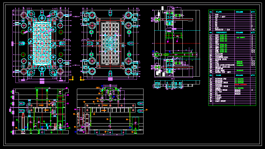
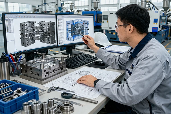
2. Conversion of CAD files from other formats
When designing an injection molded part, you need to start from the beginning and tailor each step of the product life cycle to the injection molding process.
This means you can’t just take, for example, a 3D printed file like 1. stl and convert to an injection molding format. Even if you will. stl is converted to. step file, the result will also be a 3D object initially composed of triangles, while injection molding will interpret the shape as a series of curves.
Although the reverse engineering software package can be used. STL files are converted into different formats, but they require as much expertise as designing a new part, or even more.
3. The position of the dividing line is wrong
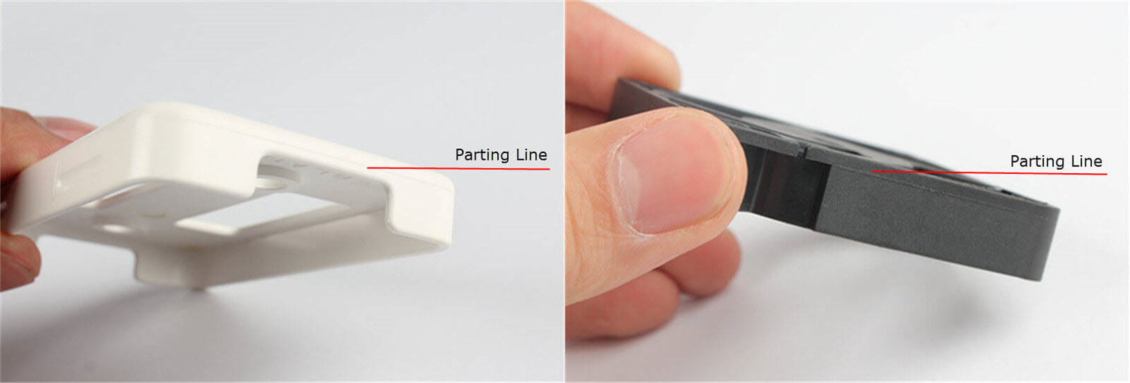
In the injection molding process, the parting line is the dividing line between the core mold and the cavity mold. Its placement will affect the success and appearance of the molded part. Improper parting line placement can cause the following problems:
- Flash, where the material leaks from the tiny gap between the core and cavity
- Additional ejection steps required
The ideal parting line should be placed along the sharp edge. This makes the lines less noticeable and reduces the chance of flashes and other undesirable effects.
Many CAD software includes parting line analysis to help you determine the ideal location. However, your software may not be able to understand the final actual application of the part, which is also an important factor when determining the position of the line.
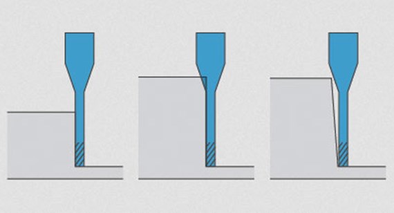
4. Use a draft less than 1 degree
During the injection molding process, the die or taper is an angle incorporated into the design to make it easier to eject the mold.
Drafting can also reduce warpage or part breakage.
One of the most common mistakes in injection molding design is to abandon drafts, or not add drafts until late in the design process, because doing so will have a negative impact on the finished design.
The rule needs to follow:
- For every inch of cavity depth, an increase of 1 degree of draft
- 5 degree vertical
- The closing temperature is above 3 degrees
Also, remember that drafting is related to the parting line: the position of the parting line must separate it so that the draft is minimal.
5. Undercuts
Parts that cannot be ejected from a simple two-part mold have undercuts, such as protrusions or recessed areas. Examples of undercuts include connecting collets on plastic containers and threads on fasteners.
If the design does not have a bottom edge, injection mold parts are easier (and cheaper) to manufacture, so every effort should be made to eliminate them from the design.
If the feature is critical to the component, there will be some workarounds, including side operations, bump offs, and scalable closures, but these will increase cost and delivery time.
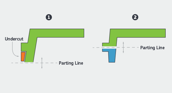
Changing the parting line can alleviate the undercutting problem. In CNC machining service, when the end mill cannot reach a certain feature due to its position, the undercut will also have problems. Some prototypes with difficult bottom edges may be suitable for 3D printing with supporting structures.
Leave A Comment