A plastic injection mold tool can cast the injected plastic into the final part, we often call it injection molding tooling. There are three critical factors that will affect the quality of plastic parts, the plastics materials, the injection machines, and the injection mold tools.
In fact, many project problems are often caused by the injection molding tool, because it needs to be created with very high precision in order to produce consistently accurate parts for the required life of the tool. There are many factors that influence good tool mold design and build, time, cost, and the location where your tool designed, all of these factors will affect the end product, which in turn can affect your end product.
Here is a complete guide to help you design the best injection mold tools for your project.
- 1) Cooling
- 2) Venting
- 3) Cavity and insert material
- 4) Runner systems
- 5) Slides and moving cores
- 6) Sensors
- 7) Ejector pins
- 8) Date stamps, part ID, and recycling symbols


1. Cooling
The primary purpose of a tool is to remove heat from the molten resin, allowing it to solidify in shape. It is effectively a large heat exchanger. Cooling facilities within the tool are therefore vitally important to get right if the tool is to run successfully.
The tool should be made so that cooling to the mold cavities allows for the required temperature of the mold to be reached with ease. A mold will heat up as it runs as the hot resin is injected time after time into the cavities. The system not only needs to be able to remove this heat but also maintain the temperature should changes occur that could alter the temperature of the cavities.
More cooling is better than not enough. Plenty of cooling channels cut into the tool gives the molding technician options for tuning of part production. In certain cases, for example, differential cooling of areas of the tool can help to reduce issues such as warping.
Consideration should be given to large sections of tools that cannot fit cooling channels in, as the part may experience warping in these areas. In such cases, inserts made of a material such as copper alloys can help to ‘pull the heat from these hard to reach areas.
Example of a cavity insert of a tool with cooling channels cut into it. The purple connections attach to a water line. Channels cut into the insert are plugged where necessary to form a ‘loop’ in which water flows around.

2. Venting
When the molten resin is injected into a cavity filled with air, the air needs somewhere to go. Vents are tiny openings in the tool cavity that allow air to seep out. If air cannot escape, it becomes compressed and can ignite, causing burn marks on the part known as ‘gassing’.
Vents are usually placed at points in the tool where the resin flow will reach last. These are areas where the air would become trapped. Venting can be done all-around part as shown here, where multiple vent ‘branches’ feeds into a peripheral channel that then exhausts to the atmosphere.
Vents can also be made through ejector pins, as the air can escape through the clearance gap between the pin and the tool.
Example of a tool inserts with venting around the part cavity. The venting channel is highlighted. The channel meets up with the cavity via small cuts to allow air to seep out. This air is then vented to the atmosphere to prevent gassing and burn marks.

3. Cavity and insert material
Tools are usually made of different types of steel. The main bulk of the tool commonly referred to as the bolster is usually made out of standard P20 tool steel. This is suitable for supporting the tool inserts against the heavy clamping loads. Cavity and core inserts can be made from a harder grade of steel, specially treated to give wear resistance.
Hardening cavities and inserts mean that their surfaces are much tougher, and can withstand constant abrasion by the plastic parts that are produced in them every day. Plastic may be much softer than steel, however, the erosion it can endure will cause deterioration over the life of the tool. Certain resins are harder on the tool cavities than others. Glass filled resins, for example, are notorious for tool wear.

4. Shrinkage
Molten plastic shrinks in size as it cools. Semi-crystalline types shrink more than amorphous. This shrinkage must be accounted for when designing and making tools for molded parts. The tool designer will increase the cavity size to compensate for the specified shrinkage of the chosen material. This is one reason why using a different resin other than that the tool has been designed for is a bad idea.

5. Runner systems
Runners are the link between the injection molding machine barrel and the gate into the cavity of the tool. They direct the flow of resin to the gate. Runners can be of differing types, depending on the application.

Cold runners
These are basically channels cut into the tool that directs the flow to the gate. They leave a ‘sprue’ (solidified plastic in the gate channels) that has to be disposed of. Some runner systems require the sprue to be manually removed. Cold runner systems are an efficient and cheap way to gate into multi-cavity tools, or into parts that require gating into multiple areas due to part size.
Hot runners
These systems use a heated cylinder that is fixed inside the tool. They keep the resin molten all the way up to the gate. The advantage of such a system is that there is no wastage of sprue to cut off the molded part and dispose of or recycle. The gate in this case is the tip of the hot runner nozzle that injects directly into the part. This gives rise to more options with features such as valve gates, which give more versatility to the molding process by allowing the gate to be closed off at any point.
Cycle times can be reduced as there are no large sprue or runners to solidify before the tool can open.

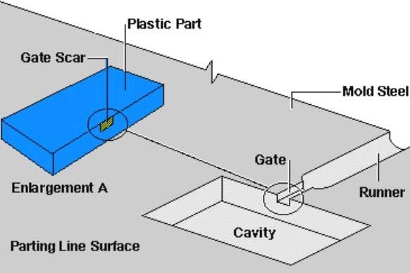
Gate types
Different applications call for the use of differing gate designs. Here are some commonly used gate types and their uses:
Sprue gate
These are simple conical tube that goes directly from the barrel nozzle into the part. They are very simple but require the remaining sprue to be trimmed off afterwards. This is wasteful unless the sprue can be recycled and takes time to remove the sprue. The sprue gate is good for filling large, deep parts as they flow through the gate can be large.
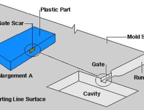
Sub gate
These gate types are useful as they allow automatic de-gating of the part. The sub gate enters the part through a small bend. As the part is pulled away when the tool opens, the gate is automatically detached from the part due to the gate being part of the fixed tool half.
Below is an example of a sub gate. As the mold opens, the gate breaks off as the part sticks to the moving half of the tool. The sprue can be either pulled or ejected out after.


Tab gate
These gate types use a simple ‘tab’ that the resin flows into as it flows into the part cavity. They are useful where cosmetic marks left on the part would prevent other gate types from being used. The tab will be left attached to the side of the part, therefore it can be trimmed with ease.

Pin gate
Pin gates leave a very small mark behind, so are good for parts where a small gate witness mark is acceptable. This gives a greater choice of gate location. These gates can be used in applications where the part will automatically detach from the gate sprue. Pin gates can, however, have lower flow and therefore introduce more stress into the molded part.

6. Slides and moving cores
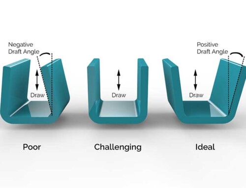
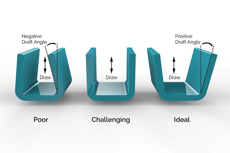
As discussed earlier, undercuts in certain molded parts would cause problems as the tool splits in two during the opening. These areas can sometimes be redesigned to remove the undercut, but where that is not possible, moving cores or slides can be used.
These are pieces of the tool that are placed in the undercut areas on the part, that can move sideways or other directions as the tool opens, allowing the tool to open and the part to be released.
Moving cores and slides can be actuated either by hydraulic cylinders, or they can be integral parts of the tool, attached to the ejector plate for example. As the ejector plate moves forward, the lifters move outwards (example shown) and allow the part to be ejected.
Moving cores and slides will increase the complexity of the tool, and therefore the cost. They also increase the likelihood of problems occurring with the tool (lifters can break if not designed to be strong enough for example).

An example of a tool with multiple slides. When the tool opens, they move in the direction shown.
7. Ejection systems
All mold tools have ejector pins to push the part out of the mold. After the tool splits open, the part will be stuck onto the core of the moving half of the tool. The injection molding machine will have a hydraulic cylinder that actuates an ejector plate (pushes it forward). The ejector plate has the ejector pins attached to it. These push forward into the part, releasing it from the core of the mold. The part then falls out of the machine.
Ejector pins leave small (usually round) marks on the part from where they sit in the tool. This should be considered in design as they will cause cosmetic defects if on a visible surface.
Preferably ejector pins should be placed all around the part, paying particular attention to deep cavity features (such as ribs) that may be more difficult to eject from the mold. Provision can be made on ribs for a place to put an ejector pin by adding material. Where possible, ejector pins should be made as large as possible. Small diameter ejector pins are prone to breaking and may need frequent replacement.


8. Sensors
Sensors are useful where the possibility exists that interference could occur with parts of the tool. For example, if an ejector plate became jammed in a forward position, and the tool attempted to close, the pins could impact the other half of the tool. Placing sensors on the moving parts of the tool helps to notify the molding technician that something is wrong. The sensors notice if a moving part is not in its expected position and disable further manufacturing until the technician has fixed the problem.
9. Date stamps, Part ID, and Recycling Symbols
Certain information is useful to have on the part. Engraving the part name or number into the tool ensures parts are identified correctly. Recycling symbols (or part material composition) help with end-of-life disposal of the part. In some countries, this is a legal requirement.
The date stamp on a part helps identify when a part was molded. This can be very helpful in solving problems with part malfunctions. For example, if bad parts are discovered, the molders can investigate what may have happened at the specific date they were made, which may have caused part issues. This traceability helps molding departments recognize and prevent further problems.

Date stamps can be installed by the toolmaker, as they are off-the-shelf parts. The most versatile is the type that allows the technician to change easily without removing them completely.
10. Conclusion
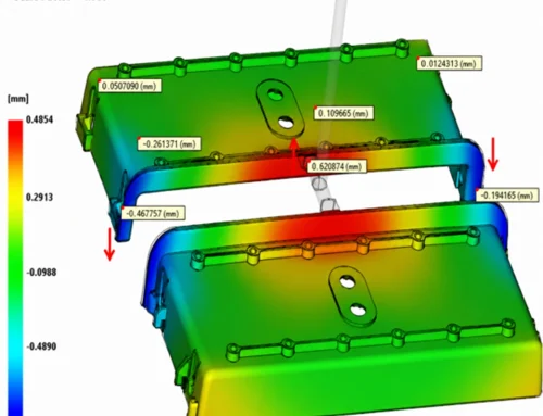
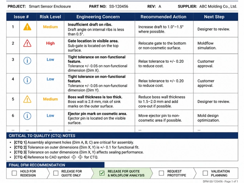
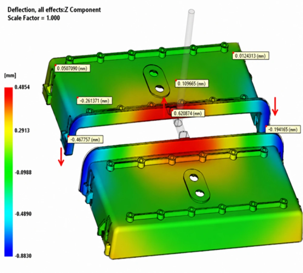
There are software programs that part or tool designers can use to assess the suitability of a part for the molding process. These can assist by predicting where problems might occur, such as air traps or excessive weld lines. The software also helps to designate temperatures and pressures expected to be required for the particular part, which will then influence molding machine selection.
For most clients, there is no need to know all these injection molding tool design details. Just ask your plastic injection molding suppliers, there are professional tool designers to help you build a plastic injection molding tool for success.